Spray Coating Methods for Thick Supercapacitor Electrodes: Fabrication, Optimization, and Biomedical Applications
This article provides a comprehensive analysis of spray coating as a scalable and versatile manufacturing technique for fabricating high-performance, thick electrodes for supercapacitors.
Spray Coating Methods for Thick Supercapacitor Electrodes: Fabrication, Optimization, and Biomedical Applications
Abstract
This article provides a comprehensive analysis of spray coating as a scalable and versatile manufacturing technique for fabricating high-performance, thick electrodes for supercapacitors. Tailored for researchers and scientists in energy storage and drug development, we explore the foundational principles of spray coating, detail advanced methodologies for achieving optimal electrode thickness and composition, and address critical troubleshooting and optimization challenges. The content further validates performance through comparative electrochemical analysis and discusses the significant implications of this technology for powering next-generation biomedical devices, from wearable sensors to implantable systems, enabling more effective clinical research and therapeutic solutions.
Spray Coating Fundamentals: Principles and Material Selection for Thick Electrode Fabrication
Spray coating has emerged as a versatile and scalable fabrication technique for producing advanced electrodes for energy storage devices, particularly supercapacitors. This solution-based processing method enables the deposition of uniform thin films of active materials onto various substrates, making it ideal for manufacturing thick supercapacitor electrodes with enhanced performance characteristics. The technique is especially valuable for processing transition metal-based electrodes, which have emerged as pivotal candidates for enhancing supercapacitor performance by addressing critical limitations in energy density, power density, and cycle stability [1] [2].
The significance of spray coating in energy storage research stems from its ability to create tailored material morphologies that optimize electrochemical properties. This method facilitates the development of innovative transition metal oxides (TMOs) including MnO₂, NiO, ZnO, Co₃O₄, VOx, and RuO₂, as well as transition metal sulfides (TMSs) including binary/ternary sulfides such as NiCo₂S₄ and CoMoS₄ [1]. These materials can be deposited as nanostructured films with features such as nanosheets and core-shell heterostructures, which significantly enhance conductivity, ion diffusion, and faradaic redox activity in supercapacitor electrodes.
Fundamental Principles and Advantages
Spray coating operates on the principle of aerosol deposition, where a precursor solution or suspension containing active materials is atomized into fine droplets and transported onto a heated substrate. Upon impact, the solvent rapidly evaporates, leaving behind a solid film of the active material. This process allows for precise control over film thickness, morphology, and composition through adjustments to solution parameters, spray conditions, and substrate temperature.
Key advantages of spray coating for supercapacitor electrodes include:
- Scalability: The technique is easily scalable from laboratory to industrial production
- Versatility: Compatible with various substrate materials and geometries
- Cost-effectiveness: Reduced material waste and lower energy requirements compared to vacuum-based methods
- Compositional control: Enables fabrication of composite and hybrid materials with synergistic effects
- Thickness control: Facilitates the development of thick electrodes (tens to hundreds of micrometers) for enhanced energy storage capacity
The compatibility of spray coating with hybrid composites such as rGO/NiO-Mn₂O₃ and CNT@MnO₂ has demonstrated significant improvements in supercapacitor performance, achieving remarkable specific capacitance (up to 1529 F g⁻¹ for ZnO@Ni₃S₂) and excellent retention rates (e.g., 91% over 500 cycles for NiO-Mn₂O₃@rGO) [1].
Experimental Protocols
Precursor Solution Preparation
Protocol 1: Aqueous Transition Metal Oxide Precursor
- Materials: Transition metal salt (e.g., Mn(CH₃COO)₂, Ni(NO₃)₂, CoCl₂), deionized water, conductive additive (e.g., carbon black), binder (e.g., PVDF)
- Procedure:
- Dissolve 0.1 M transition metal salt in 50 mL deionized water under magnetic stirring
- Add conductive additive (10-20 wt% of active material) and disperse using ultrasonication for 30 minutes
- Incorporate binder material (5-10 wt%) and continue stirring for 12 hours to ensure homogeneous dispersion
- Filter the solution through a 0.45 μm membrane to remove large aggregates
- Optimization Parameters: Solution viscosity (adjust with polymer additives), surface tension (modify with surfactants), and solid content (typically 1-5 wt%)
Protocol 2: Hybrid Composite Ink Formulation
- Materials: Pre-synthesized TMO/TMS nanoparticles, graphene oxide suspension, organic solvent (NMP or ethanol), stabilizer
- Procedure:
- Prepare 1 mg/mL graphene oxide suspension in water-ethanol mixture (1:1 ratio)
- Add TMO/TMS nanoparticles (70-80 wt% of total solid content) to the suspension
- Introduce stabilizer (0.1-0.5 wt%) to prevent agglomeration
- Sonicate the mixture using a probe sonicator (300 W, 30 minutes, pulse mode 5s on/2s off)
- Centrifuge at 3000 rpm for 10 minutes to remove any unexfoliated material
- Quality Control: Dynamic light scattering for particle size distribution, zeta potential measurement for colloidal stability
Spray Coating Deposition System
Protocol 3: Automated Spray Coating Setup
- Equipment: Ultrasonic or airbrush spray nozzle, precision syringe pump, heated substrate stage, temperature controller, nozzle moving system, compressed gas source
- System Configuration:
- Mount spray nozzle 10-20 cm above substrate surface
- Connect precursor reservoir to syringe pump for controlled feed rate (typically 1-10 mL/min)
- Set substrate temperature to 60-120°C (optimized for solvent evaporation)
- Program nozzle moving speed (5-20 cm/s) and pattern for uniform coverage
- Adjust carrier gas (N₂ or air) pressure to 10-30 psi for optimal aerosol generation
- Process Monitoring: In-situ thickness measurement via laser profilometry, infrared camera for temperature mapping
Protocol 4: Layer-by-Layer Electrode Fabrication
- Procedure:
- Pre-clean substrate (current collector) with sequential acetone, ethanol, and deionized water rinsing
- Preheat substrate to desired temperature (80°C for aqueous systems, 100-120°C for organic solvents)
- Initiate spray deposition with optimized parameters: spray duration 2-5 s, interval time 30-60 s between passes
- Repeat deposition cycles until target thickness is achieved (typically 50-200 μm)
- Perform post-annealing treatment in furnace (200-400°C for 1-4 hours in air or inert atmosphere)
- Quality Assessment: Thickness uniformity measurement, adhesion testing (tape test), visual inspection for defects
Post-Treatment and Electrode Conditioning
Protocol 5: Thermal Annealing for Crystallization
- Materials: As-sprayed electrode films, tube furnace, gas flow system (air, N₂, or Ar)
- Procedure:
- Transfer as-deposited electrodes to ceramic boat in tube furnace
- Ramp temperature at 2-5°C/min to target annealing temperature (250-450°C for TMOs, 300-500°C for TMSs)
- Maintain at target temperature for 2-6 hours under controlled atmosphere
- Cool naturally to room temperature at rate of 1-2°C/min
- Store in desiccator until cell assembly
- Characterization: XRD for crystallinity, SEM for morphology, BET for surface area
Protocol 6: Electrochemical Activation
- Setup: Three-electrode cell with sprayed electrode as working electrode, Pt counter electrode, and reference electrode
- Activation Protocol:
- Immerse electrode in electrolyte (e.g., 1M KOH, Na₂SO₄, or LiClO₄ in organic solvent)
- Perform cyclic voltammetry scanning between suitable potential window (e.g., 0-0.5V for MnO₂) for 20-50 cycles at 10 mV/s
- Alternatively, apply constant current charging-discharging for 10-20 cycles
- Rinse with solvent and dry before device assembly
- Performance Metrics: Specific capacitance calculation, cycling stability assessment
Material Systems and Performance Data
Spray coating has been successfully applied to various electrode material systems for supercapacitors, each demonstrating distinct performance characteristics:
Table 1: Performance of Spray-Coated Transition Metal Oxide Electrodes
| Material System | Specific Capacitance (F g⁻¹) | Cycling Stability | Rate Capability | Key Features |
|---|---|---|---|---|
| MnO₂ nanosheets | 450-650 | 85-92% after 5000 cycles | 65-75% at 10 A g⁻¹ | High theoretical capacitance, low cost |
| NiO nanoparticles | 350-550 | 80-88% after 3000 cycles | 60-70% at 5 A g⁻¹ | Good redox activity, moderate conductivity |
| Co₃O₄ nanostructures | 500-750 | 85-90% after 4000 cycles | 70-80% at 8 A g⁻¹ | High theoretical capacity, multiple oxidation states |
| RuO₂ composites | 600-800 | 90-95% after 10000 cycles | 75-85% at 10 A g⁻¹ | Excellent conductivity, high cost |
| VOx thin films | 400-600 | 80-87% after 3500 cycles | 65-75% at 6 A g⁻¹ | Multiple oxidation states, mixed conductivity |
Table 2: Performance of Spray-Coated Transition Metal Sulfide and Composite Electrodes
| Material System | Specific Capacitance (F g⁻¹) | Cycling Stability | Rate Capability | Key Advantages |
|---|---|---|---|---|
| NiCo₂S₄ | 1200-1529 | 88-94% after 5000 cycles | 75-85% at 15 A g⁻¹ | Superior electrical conductivity, rich redox sites |
| CoMoS₄ | 1000-1300 | 85-92% after 4500 cycles | 70-80% at 12 A g⁻¹ | Synergistic effects, enhanced kinetics |
| ZnO@Ni₃S₂ | 1400-1529 | 90-95% after 5000 cycles | 80-88% at 10 A g⁻¹ | Core-shell structure, interface engineering |
| rGO/NiO-Mn₂O₃ | 800-1100 | 91% after 500 cycles | 75-82% at 8 A g⁻¹ | Conductive network, hybrid composition |
| CNT@MnO₂ | 600-900 | 87-93% after 6000 cycles | 70-78% at 10 A g⁻¹ | Hierarchical structure, improved charge transfer |
The synergistic effects in hybrid composites significantly enhance the conductivity, ion diffusion, and faradaic redox activity, enabling these remarkable performance characteristics [1]. Transition metal sulfides generally demonstrate superior electrical conductivity and reversible kinetics compared to oxides, though challenges remain in synthesis scalability and stability.
Research Reagent Solutions and Essential Materials
Table 3: Essential Research Reagents for Spray Coating of Supercapacitor Electrodes
| Reagent Category | Specific Examples | Function in Formulation | Concentration Range | Supplier Considerations |
|---|---|---|---|---|
| Metal Precursors | Mn(CH₃COO)₂·4H₂O, Ni(NO₃)₂·6H₂O, CoCl₂·6H₂O, Zn(CH₃COO)₂, RuCl₃ | Source of active transition metal ions for TMO/TMS formation | 0.05-0.5 M in precursor solution | High purity (>99%) to minimize impurities |
| Conductive Additives | Carbon black, Super P, graphene oxide, carbon nanotubes | Enhance electrical conductivity of composite electrodes | 5-20 wt% of active material | Dispersion quality critical for performance |
| Binder Materials | PVDF, PTFE, Nafion, CMC | Provide mechanical integrity and adhesion to current collector | 5-10 wt% of total solids | Compatibility with solvent system essential |
| Solvent Systems | Deionized water, ethanol, isopropanol, NMP | Dispersion medium for precursor materials | Balance of evaporation rate and solubility | High purity to prevent contamination |
| Surfactants/Stabilizers | Triton X-100, SDS, CTAB, PVP | Improve colloidal stability and wetting properties | 0.1-1.0 wt% of solution | Minimal residual content after processing |
| Current Collectors | Carbon paper, stainless steel, Al foil, Ni foam | Provide electrical connection and mechanical support | Various thicknesses (0.1-1 mm) | Surface pretreatment enhances adhesion |
| Dopants/Additives | NH₄F, urea, thiourea | Modify morphology and structure during processing | 0.1-0.5 M in precursor solution | Control nucleation and growth processes |
Process Optimization and Characterization Techniques
Critical Process Parameters
The performance of spray-coated electrodes is highly dependent on optimization of process parameters:
Table 4: Key Spray Coating Parameters and Optimization Ranges
| Parameter | Typical Range | Influence on Electrode Properties | Optimization Strategy |
|---|---|---|---|
| Nozzle-to-substrate distance | 10-25 cm | Affects droplet size, uniformity, and evaporation rate | Adjust based on spray pattern and substrate temperature |
| Substrate temperature | 60-150°C | Controls solvent evaporation rate and film formation | Balance between rapid drying and defect formation |
| Solution flow rate | 1-10 mL/min | Determines deposition rate and film thickness per pass | Optimize for uniform coverage without flooding |
| Carrier gas pressure | 10-30 psi | Influences aerosol generation and droplet size | Higher pressure creates finer mist but increases overspray |
| Spray duration/passes | 10-100 passes | Controls total electrode thickness and mass loading | Multiple thin layers preferred over single thick deposition |
| Solution concentration | 1-10 mg/mL | Affects viscosity, stability, and deposition efficiency | Higher concentrations enable thicker films but risk clogging |
| Post-annealing temperature | 200-500°C | Determines crystallinity, composition, and conductivity | Material-dependent; balance between crystallization and decomposition |
Characterization Methods for Spray-Coated Electrodes
Comprehensive characterization is essential to correlate processing conditions with electrochemical performance:
- Structural Analysis: XRD for phase identification, Raman spectroscopy for structural defects, XPS for surface composition
- Morphological Characterization: SEM for surface morphology, TEM for nanostructure analysis, AFM for surface roughness
- Porosity Analysis: BET surface area measurement, pore size distribution analysis
- Electrochemical Evaluation: Cyclic voltammetry, galvanostatic charge-discharge, electrochemical impedance spectroscopy
- Mechanical Properties: Adhesion tests (tape test, scratch test), bending tests for flexible electrodes
Process Visualization and Workflow Diagrams
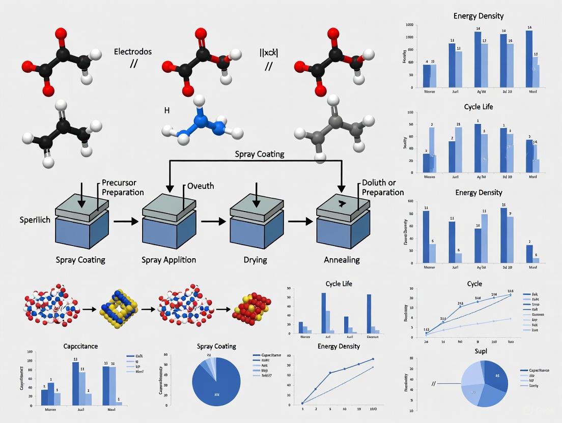
Diagram 1: Spray Coating Process Workflow
Diagram 2: Parameter-Performance Relationships
Applications and Future Perspectives
Spray-coated supercapacitor electrodes find applications across various domains, including consumer electronics, hybrid electric vehicles, and grid energy storage. The technique enables the development of flexible, wearable, and multifunctional energy storage devices that can be integrated into smart textiles, portable electronics, and Internet of Things (IoT) devices [1] [2].
Future research directions for spray coating in energy storage include:
- Development of multifunctional supercapacitors with additional capabilities (electrochromic, self-healing)
- Integration with renewable energy harvesting systems
- Implementation of artificial intelligence for process optimization and control
- Exploration of sustainable and earth-abundant electrode materials
- Scale-up to industrial manufacturing through roll-to-roll processing
The transformative potential of spray coating for transition metal-based electrodes continues to drive innovation in bridging the performance gap between capacitors and batteries, paving the way for next-generation energy storage systems [1].
The advancement of energy storage systems is pivotal for the development of wearable electronics, smart packaging, and the Internet of Things (IoT). Within this context, thick electrodes have emerged as a critical component for enhancing the performance metrics of supercapacitors and lithium-ion batteries. Electrodes with higher mass loading improve energy density by reducing the proportion of non-active materials, such as current collectors and separators, within the cell [3]. However, traditional manufacturing techniques often struggle with the inherent trade-offs between achieving high thickness and maintaining good electrochemical and mechanical properties.
Spray coating has been identified as a versatile and efficient fabrication method capable of addressing these challenges. This document delineates the key advantages of spray coating for thick electrode production, focusing on its ability to ensure conformability, enable scalable fabrication, and provide precise thickness control. Supported by experimental data and protocols, this analysis is intended to guide researchers and scientists in the optimization of next-generation energy storage devices.
Core Advantages of Spray Coating for Thick Electrodes
The spray coating method offers distinct benefits for fabricating thick electrodes, which can be categorized into three primary advantages, as summarized in the table below.
Table 1: Key Advantages of Spray Coating for Thick Electrode Production
| Advantage | Key Feature | Impact on Electrode Performance |
|---|---|---|
| Conformability | Enables fabrication of thin, flexible electrodes that conform to complex surfaces [4]. | Establishes stable electrical interfaces, reduces motion artefacts, and allows for integration into flexible/wearable electronics. |
| Scalability | A fast-throughput, industrially mature technology compatible with large-area substrates [4]. | Facilitates the transition from lab-scale research to commercial, high-volume manufacturing of energy storage devices. |
| Thickness Control | Allows for linear and predictable thickness build-up through sequential spray cycles [4]. | Provides a straightforward method to achieve high, uniform mass loading, which is directly correlated with increased capacitance and energy density. |
Quantitative Performance of Spray-Coated Electrodes
Spray-coated electrodes have demonstrated compelling performance in real devices. The following table summarizes key electrochemical data from a study on spray-coated paper supercapacitors.
Table 2: Electrochemical Performance of Spray-Coated Paper Supercapacitors [4]
| Performance Parameter | Value | Testing Condition / Note |
|---|---|---|
| Electrode Thickness Range | 1 - 10 µm | Achieved via controlled spray cycles. |
| Device Capacitance | ~0.1 F | At a current density of 1.0 A/g (electrode area: 19.6 cm²). |
| Specific Capacitance | 23.1 - 20.1 F/g | Stable across high current densities from 1.0 to 10 A/g. |
| Equivalent Series Resistance (ESR) | 0.22 - 0.27 Ω | For current densities of 0.1–5.0 A/g; indicates low internal resistance. |
| Power Density | ~104 W/kg | Enabled by low ESR. |
| Volumetric Capacitance | 6.52 F/cm³ | - |
Experimental Protocol: Spray Coating of CNF-PEDOT:PSS Thick Electrodes
This protocol details the fabrication of conformable supercapacitor electrodes based on cellulose nanofibrils (CNF) and the conducting polymer PEDOT:PSS, as validated in prior research [4].
Research Reagent Solutions
Table 3: Essential Materials and Reagents
| Item Name | Function/Description |
|---|---|
| CNF-PEDOT:PSS Ink | The active material for charge storage. A water-based ink with a PEDOT:PSS to CNF weight ratio of 2.65:1 [4]. |
| Glycerol | A plasticizer added to the ink formulation to prevent cracking of the spray-coated films during drying. |
| Carbon-coated Substrate | Serves as the current collector. Provides a conductive surface for the electrode layer and enhances adhesion. |
| Mask | Used to define the specific geometry and area of the electrode during the spray coating process. |
Step-by-Step Workflow
Step 1: Substrate Preparation and Masking
- Begin with a flexible substrate (e.g., plastic film or paper) pre-coated with a carbon adhesion layer.
- Cover the substrate with a mask to define the desired electrode area.
Step 2: Ink Formulation and Optimization
- Prepare the CNF-PEDOT:PSS ink with the specified 2.65:1 ratio.
- Modify the ink by adding glycerol as a plasticizer and adjusting water content to achieve optimal viscosity and prevent film cracking. The final formulation is critical for uniform film formation.
Step 3: Pre-Heating the Substrate
- Pre-heat the masked substrate to approximately 90°C. This temperature is sufficient to limit agglomeration of the sprayed materials and ensures swift solvent evaporation, which reduces fabrication time and improves film uniformity.
Step 4: Spray Coating Deposition
- Use a spray coater to apply the ink onto the hot, masked substrate.
- Maintain a consistent spraying pause interval to allow for proper solvent evaporation between layers.
- To control the final electrode thickness, linearly increase the number of spraying cycles or the total volume of ink deposited (e.g., 5 ml to 15 ml of ink can produce electrodes from 2.5 µm to 7.6 µm thick) [4].
Step 5: Post-Processing and Device Assembly
- After spraying, the electrode is fully dried and can be peeled off if a free-standing film is required.
- Assemble the solid-state supercapacitor by combining two spray-coated electrodes with a gel electrolyte (e.g., applied via bar coating) and a separator.
Diagram 1: Electrode Fabrication Workflow
Theoretical Foundation: Conformability and Structural Design
Conformability on Complex Surfaces
The efficacy of spray-coated thin electrodes in flexible applications is underpinned by theoretical models of conformability. For a thin-film device to attach seamlessly to a rough biological surface (a model for any complex, flexible surface), the total energy of the conformal system must be negative: U_total = U_bending + U_skin + U_adhesion < 0 [5]. This criterion is met when the device has a low effective bending stiffness (EI), which is a function of both the material's Young's modulus and the device thickness. Spray coating directly facilitates this by enabling the fabrication of ultra-thin (e.g., 1-10 µm) electrode layers [4], significantly reducing bending stiffness and promoting conformal contact.
Overcoming Thickness Limitations with Structural Design
While increasing thickness boosts energy density, it introduces challenges like the Limited Penetration Depth (LPD), where ion diffusion becomes a bottleneck, and the Critical Cracking Thickness (CCT), which leads to mechanical failure [3]. Spray coating can be integrated with innovative structural designs to overcome these limitations, as illustrated below.
Diagram 2: Challenges and Design Solutions
Strategies to overcome LPD include designing electrodes with low-tortuosity, aligned pores or creating gradient porosity structures, which can be achieved through controlled deposition and patterning during spray coating [6] [3]. To address CCT, solvent-free dry film technologies based on binder fibrillation have been developed, producing thick electrodes (50-1000 µm) without cracks, as they avoid capillary stresses entirely [7].
Spray coating stands out as a highly effective manufacturing technique for thick electrodes, directly addressing the core requirements of modern energy storage research. Its ability to produce thin, conformable layers enables the development of flexible electronics, while its inherent scalability and precise thickness control make it suitable for industrial adoption. By integrating the material formulations and protocols outlined in this document, researchers can leverage spray coating to push the boundaries of areal capacity and energy density in supercapacitors and batteries, thereby accelerating the development of advanced powered devices.
The development of high-performance, thick-film electrodes via spray coating is a cornerstone of advancing flexible and wearable energy storage devices. This manufacturing paradigm demands precise formulation of functional inks, where each component is selected to fulfill a specific electrochemical, structural, or processing role. The synergistic combination of conducting polymers for high pseudocapacitance, carbon nanomaterials for electrical conductivity and structural integrity, and specialized binders for mechanical cohesion dictates the final electrode's performance. Spray coating has emerged as a particularly attractive fabrication technique due to its ability to produce uniform, conformal films over large areas, compatibility with flexible substrates, and suitability for scalable, roll-to-roll manufacturing [8] [9]. The successful translation of laboratory-scale concepts into practical devices hinges on a deep understanding of these critical ink components and their processing protocols, which are detailed in this application note.
Critical Ink Component Classes and Their Functions
Conducting Polymers
Conducting polymers (CPs) are organic materials that provide a unique combination of metal-like electronic conductivity and the mechanical flexibility and processability of plastics. In supercapacitor electrodes, their primary function is to contribute high pseudocapacitance via fast and reversible redox reactions [10].
- Poly(3,4-ethylenedioxythiophene):Polystyrene Sulfonate (PEDOT:PSS): This commercially available, water-dispersible CP is widely used in sprayable inks. It functions as a polymeric mixed conductor, supporting both electronic and ionic transport. Its high conductivity (up to ~1000 S/cm) and excellent film-forming properties make it ideal for creating flexible, conductive networks [10] [8]. Formulations often incorporate additives like ethylene glycol to enhance its conductivity.
- Polyaniline (PANI) and Polypyrrole (PPy): These CPs are valued for their high theoretical specific capacitance. However, they often suffer from volumetric changes during cycling that can reduce long-term stability. They are frequently combined with carbon nanomaterials to create composite structures that mitigate this issue and enhance overall conductivity [10] [11].
Table 1: Key Conducting Polymers for Supercapacitor Inks
| Polymer | Function | Key Advantages | Reported Performance |
|---|---|---|---|
| PEDOT:PSS | Pseudocapacitive material, Mixed ionic-electronic conductor | High conductivity, excellent stability, commercial availability, good film-forming | Areal capacitance: 9.1 mF/cm² in paper-based devices [8] |
| Polyaniline (PANI) | Pseudocapacitive material | Very high theoretical capacitance, tunable conductivity | Specific capacitance: 100–2000 F/g in composites [11] |
| Polypyrrole (PPy) | Pseudocapacitive material | Good specific capacitance, relatively straightforward polymerization | Used in ternary composites with GO and metal oxides [11] |
Carbon Nanomaterials
Carbon nanomaterials serve as the backbone of the electrode, providing electrical conductivity, high surface area for charge storage, and a porous scaffold for ion transport. They are essential for building the thick, three-dimensional structures required for high energy density.
- MXenes: A class of two-dimensional transition metal carbides/nitrides, MXenes such as Ti₃C₂Tₓ offer exceptionally high metallic conductivity, hydrophilicity, and high volumetric capacitance. Their solution processability makes them excellent candidates for formulating stable, high-performance inks without the need for additives or surfactants. Reported specific capacitance values for MXene-based electrodes range from 100 to 1000 mF/cm² [12].
- Carbon Nanotubes (CNTs): Single-walled (SWCNTs) and multi-walled (MWCNTs) carbon nanotubes form highly conductive percolation networks. Their high aspect ratio and mechanical strength are crucial for flexible electrodes. They can be dispersed in water using nanostructured biopolymers like cellulose nanocrystals (CNCs), enabling green and sustainable ink formulation [13].
- Onion-Like Carbon (OLC): This metal-free carbon nanomaterial consists of concentric, spherical carbon shells. It is valued for its high conductivity and stability. Spray-coated OLC electrodes have demonstrated specific capacitances of 24.1 F/g with excellent retention (98% after 10,000 cycles) [14].
Table 2: Key Carbon Nanomaterials for Supercapacitor Inks
| Material | Function | Key Advantages | Reported Performance |
|---|---|---|---|
| MXenes (e.g., Ti₃C₂Tₓ) | Conductive backbone, Pseudocapacitive material | Metallic conductivity, hydrophilicity, high volumetric capacitance | Specific capacitance: 100–1000 mF/cm² [12] |
| Carbon Nanotubes (CNTs) | Conductive network, Structural reinforcement | High aspect ratio, mechanical strength, high conductivity | Sheet resistance: <130 Ω/□ in CNT/biopolymer films [13] |
| Onion-Like Carbon (OLC) | EDLC material, Conductive additive | Metal-free, high stability, good conductivity | Specific capacitance: 24.1 F/g; 98% retention after 10k cycles [14] |
| Acetylene Black (AB) | Conductive additive, Surface area enhancer | Low cost, high conductivity, nanoparticles increase surface area | Current density: 1.95 mA/cm² in microbial electrochemical systems [15] |
Binders and Dispersion Agents
Binders are indispensable for integrating active components into a mechanically robust, adherent film, particularly for thick electrodes. Dispersion agents ensure the stability and homogeneity of the ink.
- Cellulose Nanofibrils (CNFs) and Nanocrystals (CNCs): These nanostructured biopolymers are emerging as sustainable, high-performance alternatives to synthetic binders. CNFs create a nanoporous polymeric scaffold that provides mechanical strength and high porosity, facilitating high mass loading [8]. CNCs are highly effective at dispersing carbon nanomaterials like CNTs in water, replacing toxic solvents or surfactants. They form stable colloidal suspensions that are ideal for spray coating [13].
- Ionic Polymers (e.g., Nafion): These polymers are used in small quantities to improve adhesion to substrates and enhance the ink's stability. For example, Nafion is used in spray suspensions for acetylene black to ensure uniform coating on stainless steel mesh [15].
Experimental Protocols for Ink Formulation and Electrode Fabrication
Protocol 1: Formulating a PEDOT:PSS/CNF Composite Ink for Spray Coating
This protocol details the creation of a homogeneous, sprayable ink for flexible paper-based supercapacitors [8].
Ink Preparation:
- Materials: PEDOT:PSS (e.g., Clevios PH1000), Cellulose Nanofibrils (CNF, 0.52 wt% dispersion in water), Ethylene Glycol (EG), Glycerol, Hydroxyethyl Cellulose (HEC), distilled water.
- Dilute the CNF dispersion to 0.1 wt% using distilled water.
- Mix PEDOT:PSS with 5 wt% Ethylene Glycol (conductivity enhancer).
- Combine the diluted CNF and PEDOT:PSS/EG mixture.
- Add small amounts of Glycerol and HEC as rheology modifiers to control viscosity and prevent cracking during drying.
- Stir the final mixture at room temperature until a homogeneous ink is achieved.
Spray Coating Deposition:
- Utilize an industrial air-atomizing spray system for superior film uniformity and minimal clogging.
- Use a layer-by-layer deposition strategy to build electrode thickness controllably.
- Key Parameters: Nozzle type, air pressure, substrate temperature, and nozzle-to-substrate distance must be optimized for consistent droplet size and even film formation.
Post-Processing:
- Allow the coated film to dry at room temperature or on a heated plate.
- The resulting electrode is a flexible, homogeneous film of PEDOT:PSS/CNF, ready for device assembly.
Protocol 2: Aqueous Processing of CNT Films using Nanostructured Biopolymers
This green chemistry protocol disperses CNTs without functionalization, preserving their intrinsic electrical properties [13].
Dispersant Synthesis:
- Type I CNCs: Prepare via rapid addition of H₂SO₄ to microcrystalline cellulose, followed by a 10-minute reaction at 70°C.
- Type II CNCs: Prepare via slow addition of H₂SO₄ with a 1-hour reaction at ambient temperature.
- Chitin Nanocrystals (ChNCs): Prepare by refluxing chitin powder in 3M HCl at 120°C for 90 minutes.
- Purify all dispersants via dialysis against ultrapure water until neutral pH is reached.
CNT Ink Formulation:
- Mix 1 g L⁻¹ of SWCNTs or surface-conditioned MWCNTs with 1–5 g L⁻¹ of the synthesized biopolymer (CNC or ChNC) in ultrapure water.
- Subject the mixture to probe sonication to exfoliate and disperse the CNTs, forming a stable colloidal ink.
Spray Coating and Thermal Treatment:
- Spray the aqueous CNT/NB dispersion onto the target substrate.
- To enhance electrical properties, subject the deposited film to a thermal treatment at 450 °C under an inert atmosphere (e.g., N₂ or Ar). This step pyrolyzes the non-conductive biopolymer matrix, increasing direct contacts between CNTs and resulting in lower sheet resistance and higher electrochemically active surface area.
Protocol 3: Spray Coating of Onion-Like Carbon (OLC) for Metal-Free Supercapacitors
This protocol outlines the fabrication of a sustainable, fully carbon-based supercapacitor electrode [14].
OLC Ink Preparation:
- Dispense OLC powder in a suitable solvent (often aqueous-based) to create a stable spray suspension.
- Additives may be included to adjust rheology and prevent particle agglomeration.
Electrode Fabrication:
- Spray the OLC ink uniformly onto a carbon paper current collector. This combination avoids heavy metal foils, enhancing sustainability and energy density.
- Dry the coated electrode to remove solvents.
Performance:
- The resulting OLC/carbon paper electrode outperforms traditional aluminum foil counterparts, especially at high scan rates, demonstrating the viability of metal-free architectures.
The Scientist's Toolkit: Essential Research Reagent Solutions
Table 3: Key Reagents for Spray-Coatable Supercapacitor Inks
| Reagent / Material | Function / Role | Example Use Case |
|---|---|---|
| PEDOT:PSS (Clevios PH1000) | Primary conductive polymer; provides pseudocapacitance and hole transport | Main active material in flexible paper supercapacitors [8] |
| Cellulose Nanofibrils (CNF) | Sustainable binder & structural scaffold; provides porosity & mechanical strength | Creates nanoporous network in PEDOT:PSS composites [8] |
| Cellulose Nanocrystals (CNC) | Aqueous dispersing agent for carbon nanomaterials; green alternative to surfactants | Stabilizes CNTs in water for conductive film fabrication [13] |
| Carbon Nanotubes (SW/MW) | Conductive additive & structural backbone; forms charge percolation network | Spray-coated conductive films after dispersion with CNC/ChNC [13] |
| Ethylene Glycol (EG) | Secondary dopant; improves conductivity of PEDOT:PSS | Added to PEDOT:PSS ink to enhance electronic transport [8] |
| Nafion Solution | Ionic polymer binder; improves adhesion & ink stability | Binds acetylene black nanoparticles to stainless steel mesh [15] |
| Onion-Like Carbon (OLC) | Metal-free active material; charge storage via electric double-layer | Sustainable active material sprayed on carbon paper [14] |
Workflow and Component Interaction Diagrams
Ink Component Interaction Workflow
This diagram illustrates the synergistic relationship between the three critical ink components and how they contribute to the final electrode's properties through the spray coating fabrication process. Conducting polymers directly enable high capacitance, carbon nanomaterials provide conductivity and influence porosity, while binders are critical for mechanical robustness and structural control. The spray coating process integrates these components to realize the final functional electrode.
The Role of Substrate and Current Collectors in Electrode Performance and Flexibility
In the development of advanced energy storage devices, the design of thick electrodes via spray coating methods is a key strategy for enhancing energy density. While significant research focus is placed on active materials, the substrate and current collector play equally critical roles. These components provide the essential mechanical support for thick active material layers and ensure efficient electron transport, directly influencing the electrode's electrochemical performance, mechanical integrity, and flexibility. This application note examines the function of substrates and current collectors within the context of spray-coated thick supercapacitor electrodes, providing structured performance data and detailed experimental protocols for researchers.
Performance and Material Selection Guide
The choice of substrate and current collector is a balance of electrical, electrochemical, and mechanical properties. The following tables summarize key characteristics and performance data of common materials.
Table 1: Characteristics of Common Substrates and Current Collectors
| Material | Key Properties | Primary Role | Advantages | Limitations |
|---|---|---|---|---|
| Metal Foils (Al, Cu) | High electrical conductivity, smooth surface | Current Collector | Low equivalent series resistance (ESR), industry standard | Limited intrinsic flexibility, prone to work-hardening cracks |
| Paper/Cellulose | Fibrous, porous, moderate surface roughness | Integrated Substrate & Collector | Green material, flexible, forms a mechanical bond with active materials [4] | Lower conductivity often requires a secondary conductive layer |
| PET/Plastic with Metal Coating | Flexible polymer base with thin conductive layer | Flexible Current Collector | Excellent flexibility, lightweight | Delamination risk under severe bending, more complex fabrication |
| Carbon-Based Layers | Conductive, porous, can be applied as a coating | Interfacial Layer | Improves adhesion, creates a more uniform electric field [4] [8] | Adds a manufacturing step, increases total electrode thickness |
Table 2: Impact on Supercapacitor Performance
| Material Configuration | Reported Performance Metric | Value | Key Implication |
|---|---|---|---|
| Al/C current collector with spray-coated CNF/PEDOT:PSS [4] | Equivalent Series Resistance (ESR) | 0.22 Ω | Excellent interfacial contact enables high power density (~104 W/kg) |
| Spray-coated paper electrode [8] | Areal Capacitance | 9.1 mF/cm² | Homogeneous, thin films are suitable for high-quality, flexible electrodes |
| Spray-coated paper electrode [8] | Equivalent Series Resistance (ESR) | 0.3 Ω | Low resistance is achievable with optimized spray coating and materials |
Experimental Protocols
Protocol: Fabrication of Spray-Coated Paper-Based Electrodes
This protocol details the creation of flexible, paper-based electrodes using a spray-coating technique, suitable for producing high-performance supercapacitors with low equivalent series resistance [4] [8].
Workflow: Spray-Coated Paper Electrode Fabrication
Materials and Reagent Solutions
- Cellulose Nanofibrils (CNF): Acts as a nanostructured bio-template and binder, providing mechanical strength and a high-surface-area scaffold [4] [8].
- PEDOT:PSS (e.g., Clevios PH1000): A conductive polymer serving as the primary active charge storage material [8].
- Ethylene Glycol (EG): A conductivity enhancer for PEDOT:PSS (used at 5 wt%) [8].
- Glycerol: A plasticizer (used at 8 wt%) to prevent film cracking and improve flexibility [4].
- Aluminum-coated PET or Carbon-coated substrate: Functions as the flexible current collector [4] [8].
Step-by-Step Procedure
- Ink Formulation: Dilute a CNF solution to 0.1 wt% in deionized water. Separately, mix PEDOT:PSS with 5 wt% Ethylene Glycol. Combine the CNF and PEDOT:PSS/EG mixtures, then add Glycerol to a final concentration of 8 wt% of the total ink weight. Stir the final mixture for 2-4 hours to ensure homogeneity [4] [8].
- Substrate Preparation: Clean the current collector (e.g., Al/PET) with isopropanol and plasma treat if necessary to improve wettability and adhesion. Secure the substrate on a heated plate at 90°C, using a mask to define the electrode area [4].
- Spray Coating: Load the prepared ink into an industrial air-atomizing spray system. Use a layer-by-layer deposition strategy, allowing brief solvent evaporation between passes. Control the final electrode thickness (e.g., 1–10 µm) by adjusting the number of spray cycles or total ink volume [4] [8].
- Post-Processing: After deposition, dry the electrodes thoroughly in an oven at 70-80°C for 15-30 minutes to remove residual solvent and ensure stable adhesion [8].
Protocol: Adhesion and Flexibility Testing
Evaluating the mechanical robustness of the electrode layer on its substrate is critical for flexible applications.
Materials and Equipment
- Prepared electrode samples
- Adhesive tape (e.g., 3M Scotch tape)
- Peel test apparatus
- Bending apparatus (mandrel or custom fixture)
- Electrochemical workstation (for in-situ testing)
Step-by-Step Procedure
- Adhesion Test (Peel Test): Firmly press a standardized adhesive tape onto the surface of the coated electrode. Pull the tape back at a 180° angle at a controlled speed (e.g., 10 mm/min) using a tensile tester. Measure the force required for delamination. Alternatively, perform a qualitative check by repeatedly applying and removing tape; a robust electrode will show no significant material transfer [16].
- Flexibility Test (Bending Test): Mount the electrode on a bending fixture with a defined curvature radius. Subject the electrode to repeated bending cycles (e.g., 100 to 10,000 cycles). After bending, perform ex-situ electrochemical characterization (e.g., EIS and CV) to monitor changes in resistance and capacitance. For a more advanced analysis, perform in-situ electrochemical measurements during bending [8].
- Data Analysis: Calculate the capacitance retention and percentage change in ESR after bending cycles. Electrodes for wearable applications should typically retain >90% of their initial capacitance after thousands of bending cycles.
Protocol: Electrochemical Impedance Spectroscopy (EIS) for Interface Analysis
EIS is a powerful technique for characterizing the quality of the interface between the active material and the current collector.
Materials and Equipment
- Potentiostat/Galvanostat with EIS capability
- Two-electrode or three-electrode cell setup
- Prepared electrode sample as working electrode
Step-by-Step Procedure
- Cell Setup: Assemble an electrochemical cell using the prepared electrode as the working electrode. A suitable counter electrode and reference electrode complete the setup in a three-electrode configuration. For device-level analysis, a symmetric two-electrode cell can be used [4].
- Measurement: Apply a small AC amplitude (e.g., 10 mV) over a frequency range from 100 kHz to 10 mHz at the open-circuit potential.
- Data Fitting: Fit the resulting Nyquist plot to an equivalent circuit model. A key parameter is the Equivalent Series Resistance (ESR), which includes the intrinsic resistance of the active material, the ionic resistance of the electrolyte, and the contact resistance at the current collector-electrode interface. A low high-frequency real-axis intercept indicates good interfacial contact [4].
The Scientist's Toolkit
Table 3: Essential Research Reagents and Materials
| Item | Function/Role | Example Usage & Notes |
|---|---|---|
| Cellulose Nanofibrils (CNF) | Biodegradable structural scaffold | Provides mechanical support for thick electrodes; forms a porous network for ion transport [4] [8]. |
| PEDOT:PSS | Conductive polymer / Active material | Offers high capacitance and conductivity; can be modified with additives for enhanced performance [4] [8]. |
| Ethylene Glycol (EG) | Secondary dopant / Conductivity enhancer | Increases the electrical conductivity of PEDOT:PSS films [8]. |
| Glycerol | Plasticizer | Prevents cracking in spray-coated films during drying, crucial for achieving thick, defect-free layers [4]. |
| Aluminum-coated PET | Flexible current collector | Provides a conformable and lightweight base for flexible devices [4] [8]. |
| Carbon Paste/Ink | Interfacial adhesion layer | Spray-coated or printed between the substrate and active material to improve adhesion and lower contact resistance [4]. |
The substrate and current collector are foundational components that dictate the performance ceiling of spray-coated thick film electrodes. A successful design strategy must integrate these components with the active material from the outset, rather than treating them as passive supports. The protocols outlined herein provide a framework for systematically evaluating and optimizing these critical interfaces, enabling the development of next-generation, high-performance flexible energy storage devices.
Understanding the Relationship Between Electrode Thickness, Capacitance, and Internal Resistance
The design of high-performance supercapacitors (SCs) necessitates a nuanced understanding of the interplay between electrode architecture and electrochemical properties. The push towards thick electrodes (typically >10 mg cm⁻² mass loading or several tens to hundreds of microns) is driven by the imperative to enhance energy density by increasing the proportion of active material and reducing inactive components within a cell [17] [18]. However, increasing electrode thickness introduces complex trade-offs among specific capacitance, areal capacitance, and internal resistance, which collectively determine the power density and efficiency of the device. This application note, framed within research on spray coating methods, delineates these critical relationships and provides standardized protocols for the fabrication and electrochemical analysis of thick film electrodes.
Fundamental Relationships and Trade-offs
The relationship between electrode thickness, capacitance, and resistance is governed by the kinetics of ion and electron transport through the porous electrode matrix. Spray coating enables precise, layer-by-layer construction of these thick films, allowing for control over their microstructure [4] [18].
Capacitance Behavior: Gravimetric (or specific) capacitance (F g⁻¹) often decreases with increasing electrode thickness. This is attributed to longer ion diffusion pathways and the inaccessibility of deep pore structures within the active material at higher charge-discharge rates, leading to insufficient utilization of the entire active mass [18]. In contrast, areal capacitance (F cm⁻² or mF cm⁻²) generally increases with thickness, as a greater mass of active material is deposited per unit area, provided the ionic conductivity within the pore network is maintained. Studies on spray-coated carbon electrodes have demonstrated areal capacitances of 1428 mF cm⁻² at 0.3 mm thickness and 2459 mF cm⁻² at 0.6 mm thickness [18].
Internal Resistance: Electrode thickness directly impacts the device's Equivalent Series Resistance (ESR). Thicker electrodes increase the tortuous paths for ion diffusion, thereby elevating ionic resistance. Furthermore, if the electronic conductivity of the composite is not optimized, electronic resistance can also become significant. High internal resistance manifests as a large voltage drop (iR drop) during discharge, reducing power efficiency and achievable energy density. Spray-coated electrodes using conductive polymers like CNF-PEDOT:PSS have achieved low ESR values of 0.22–0.27 Ω, which is crucial for high power delivery (~10⁴ W kg⁻¹) [4].
The following diagram illustrates the core scientific concepts and performance trade-offs involved in designing thick electrodes.
Quantitative Performance Data
The table below consolidates key performance metrics from recent studies on thick supercapacitor electrodes fabricated via spray coating and other methods, highlighting the correlation between thickness, capacitance, and resistance.
Table 1: Performance Metrics of Thick Supercapacitor Electrodes
| Electrode Material | Fabrication Method | Thickness | Specific Capacitance | Areal Capacitance | Internal Resistance (ESR) | Reference |
|---|---|---|---|---|---|---|
| Activated Carbon (YP50F) with CSP/CMC | Spray Coating | 0.3 mm | - | 1428 mF cm⁻² | - | [18] |
| Activated Carbon (YP50F) with CSP/CMC | Spray Coating | 0.6 mm | - | 2459 mF cm⁻² | - | [18] |
| CNF-PEDOT:PSS | Spray Coating | 7.6 µm | 20.1–23.1 F g⁻¹ (at high rates) | 5.2 mF cm² | 0.22–0.27 Ω | [4] |
| Onion-like Carbon (OLC) on Carbon Paper | Spray Coating | - | 24.1 F g⁻¹ | 34.9 mF cm² | - | [14] |
| rGO/NiO-Mn₂O₃ Composite | Not Specified | - | - | - | 91% retention over 500 cycles | [1] |
| ZnO@Ni₃S₂ Composite | Not Specified | - | ~1529 F g⁻¹ | - | - | [1] |
Experimental Protocol: Spray Coating of Thick Carbon Electrodes
This protocol details the fabrication of thick, porous carbon electrodes via spray coating, adapted from published methodologies [14] [18].
Reagent Preparation: Carbon Slurry
- Active Material: Combine Activated Carbon (AC) powder (e.g., Kuraray YP50F, SSA ~1692 m² g⁻¹) and a conductive additive like Carbon Black Super P or Carbon Nanotubes (CNTs) in a weight ratio of 85:10 [18].
- Binder: Add 5 wt% binder to the dry mixture. For aqueous slurries, use Carboxymethyl Cellulose (CMC); for organic solvent-based slurries, use Polyvinylidene Fluoride (PVDF) or its co-polymer [18].
- Dispersant: Use de-ionized water (for CMC) or 1-Methyl-2-pyrrolidone (NMP) (for PVDF) as the solvent.
- Mixing: Stir the combined mixture for 12 hours using a magnetic stirrer or planetary mixer to achieve a homogeneous, spreadable slurry with appropriate viscosity for spraying [18].
Substrate Preparation and Coating
- Current Collector: Cut Aluminum foil or carbon paper to desired dimensions. Clean ultrasonically in isopropanol and dry thoroughly.
- Masking: Affix a mask (e.g., Kapton tape) to the substrate to define the active coating area.
- Spray Coating Setup: Secure the substrate on a hot plate maintained at 60–90°C [4] [18]. Load the prepared slurry into an airbrush or spray gun.
- Film Deposition: Apply the slurry in multiple, light passes using a spray gun (e.g., 0.5 mm nozzle) at a controlled pressure (e.g., 1–2 bar). Maintain a consistent distance (~15–20 cm) between the nozzle and substrate. Allow solvent to evaporate between passes to prevent cracking and promote uniform layer-by-layer build-up. Electrode thickness is controlled by the number of spray passes [4].
Post-Coating Processing
- Drying: After the final coat, dry the electrode completely in an oven at 60–80°C for 12 hours to remove residual solvent.
- Calendering (Optional): For some applications, a calendering process may be applied to control density and porosity, though this must be optimized to avoid excessive pore blockage [17].
- Electrode Assembly: Punch the coated film into discs of required size (e.g., 12 mm diameter) for assembly into coin cells (CR2032) in an argon-filled glove box.
The workflow for the fabrication and testing of spray-coated thick electrodes is summarized in the following diagram.
Electrochemical Characterization Protocols
Standardized electrochemical testing is critical for evaluating the performance relationships in thick electrodes.
Cyclic Voltammetry (CV)
- Purpose: To assess capacitive behavior, redox activity, and rate capability.
- Procedure: Perform CV measurements in a two-electrode cell configuration. Scan across a stable voltage window (e.g., 0–0.8 V for aqueous electrolytes) at varying scan rates (e.g., 5–100 mV s⁻¹) [4].
- Data Analysis: Calculate specific capacitance from the integrated area of the CV curve. The retention of a rectangular box-like shape at high scan rates indicates good ion response and low ESR [4] [19].
Galvanostatic Charge-Discharge (GCD)
- Purpose: To determine capacitance, cycling stability, and internal resistance.
- Procedure: Charge and discharge the cell at constant current densities across a range of values (e.g., 0.1–5.0 A g⁻¹) [4].
- Data Analysis:
- Capacitance Calculation: Calculate from the discharge time.
- Internal Resistance (ESR): Determine from the initial voltage drop (iR drop) at the beginning of the discharge curve using the formula: ESR = ΔV / (2 × I), where I is the discharge current [4].
- Cycle Life: Perform thousands of GCD cycles (e.g., 10,000) to evaluate capacitance retention [14].
Electrochemical Impedance Spectroscopy (EIS)
- Purpose: To deconvolute the contributions of ionic and electronic resistance.
- Procedure: Apply a small AC voltage amplitude (e.g., 10 mV) over a frequency range from 100 kHz to 10 mHz [4].
- Data Analysis: The high-frequency real-axis intercept in the Nyquist plot gives the ESR. The slope of the low-frequency line and the diameter of the semicircle provide insights into ion diffusion (tortuosity) and charge-transfer resistance, respectively [20] [19].
The Scientist's Toolkit: Research Reagent Solutions
Table 2: Essential Materials for Spray-Coated Thick Electrodes
| Material/Reagent | Function | Example Specifications & Notes |
|---|---|---|
| Activated Carbon (AC) | Primary active material for charge storage. | High surface area (e.g., YP50F, ~1692 m² g⁻¹). Dominantly used in EDLCs [18]. |
| Conductive Carbon Additives | Enhances electronic conductivity within the electrode matrix. | Carbon Black (e.g., Super P), Carbon Nanotubes (CNTs). Typically 10-15% of solid content [18]. |
| Polymer Binder | Provides mechanical integrity and adhesion to the current collector. | CMC (water-based) or PVDF (solvent-based). Low binder content (5-10%) is critical to avoid pore blocking [18]. |
| Current Collector | Provides electrical connection and mechanical support. | Aluminum foil (standard) or Carbon paper (for flexible, metal-free designs) [14] [18]. |
| Spray Coating Solvent | Disperses solid components to form a sprayable slurry. | De-ionized Water (with CMC) or NMP (with PVDF). Water-based is more sustainable [17] [18]. |
Advanced Fabrication Protocols and Real-World Applications in Biomedicine
The development of high-performance thick film electrodes is critical for advancing modern flexible electronics, as they are key to achieving high energy density in devices like supercapacitors. Spray coating has emerged as a dominant fabrication technique, prized for its ability to produce large-area, uniform thin films with controlled thickness from functional nanomaterial inks [21] [4]. This protocol details a comprehensive sequential production framework, from initial ink formulation to final spray deposition and device integration, specifically tailored for the fabrication of thick supercapacitor electrodes. The methods outlined leverage the advantages of spray coating—including its compatibility with a wide range of substrates, scalability, and capacity for thickness control—while addressing common challenges such as ink stability, adhesion, and the management of rheological properties [4] [22]. The goal is to provide a reliable, reproducible pathway for creating robust, high-capacitance energy storage devices.
Ink Formulation and Preparation Protocols
The performance of a spray-deposited electrode is fundamentally determined by the quality and properties of the precursor ink. A well-formulated ink must balance colloidal stability, appropriate rheology for the chosen deposition method, and final electrochemical activity.
Carbon-Based Conductive Ink
Carbon-based inks, utilizing materials like graphene, carbon nanotubes (CNTs), and carbon black, are common for electrical double-layer capacitor (EDLC) electrodes [21].
- Base Material Preparation: Begin by synthesizing or procuring the carbon nanomaterial. For graphene, this often involves the synthesis of graphene oxide (GO) via Hummers' method followed by reduction to form conductive reduced GO (rGO) [21].
- Dispersion: Disperse the carbon material in a suitable solvent, such as deionized water, N-methyl-2-pyrrolidone (NMP), or isopropyl alcohol (IPA). A typical solid content may range from 2-10 mg/mL [21].
- Additive Incorporation: To enhance stability and prevent re-agglomeration, add dispersants like sodium dodecyl sulfate (SDS) or polymers such as polyvinylpyrrolidone (PVP) at ~5-10 wt% relative to the carbon material [21].
- Homogenization: Subject the mixture to prolonged probe sonication (e.g., 1 hour at 300-500 W) or high-shear mixing to exfoliate layers and achieve a stable, homogeneous dispersion.
- Rheology Modification: For spray coating, the ink viscosity should typically be in the range of 1-100 cP [22]. Adjust the water content or add thickeners like carboxymethyl cellulose (CMC) to achieve the target viscosity.
MXene Ink
MXenes like Ti₃C₂Tₓ offer high conductivity and pseudocapacitance [22].
- Synthesis: Etch the parent MAX phase (e.g., Ti₃AlC₂) using a minimally intensive layer delamination (MILD) method with an etchant like LiF/HCl to produce multilayer MXene flakes [22].
- Delamination and Size Selection: Gently shake the multilayer sediment in deionized water to delaminate it into few-layer flakes. To ensure compatibility with aerosol jet printing nozzles, perform controlled bath sonication to reduce the flake size, balancing the need for a short ion diffusion path with the negative impact of smaller flakes on conductivity [22].
- Ink Formulation: Centrifuge the dispersion to remove large aggregates and concentrate the supernatant. The final ink is formulated without binders or additives to maximize electrochemical performance, relying on the inherent stability and rheology of the MXene aqueous dispersion [22].
PEDOT:PSS-CNF Composite Ink
This composite combines the conductive polymer with cellulose nanofibrils (CNF) for a flexible, "power paper" electrode [4].
- Solution Preparation: Mix pristine PEDOT:PSS with CNF in a weight ratio of 2.65:1 (PEDOT:PSS to CNF) in deionized water [4].
- Plasticizer Addition: To prevent film cracking during the fast drying process inherent to spray coating, incorporate a plasticizer such as glycerol. An optimized formulation includes glycerol and adjusted water content to manage surface tension and film formation [4].
- Filtration: Filter the final ink through a 0.45 μm polyvinylidene fluoride (PVDF) membrane to remove any large aggregates before deposition [23].
Table 1: Summary of Key Ink Formulations for Spray Deposition
| Ink Type | Key Components | Solvent | Key Additives & Functions | Target Viscosity |
|---|---|---|---|---|
| Carbon-Based | Graphene, CNTs, Carbon Black | Water, NMP, IPA | SDS/PVP (Dispersant) | 1 - 100 cP [22] |
| MXene | Ti₃C₂Tₓ | Water | Additive-free for performance | Compatible with AJP [22] |
| PEDOT:PSS-CNF | PEDOT:PSS, Cellulose Nanofibrils | Water | Glycerol (Plasticizer) | Optimized for spray [4] |
Substrate Preparation and Priming
Adhesion between the sprayed film and the substrate is critical for mechanical integrity, especially in flexible devices.
- Substrate Cleaning: Clean the substrate (e.g., FTO glass, flexible plastic, or carbon yarn) ultrasonically in acetone, followed by isopropanol, for 15-20 minutes each to remove organic contaminants [24] [23].
- Surface Activation: Treat the cleaned substrate with oxygen plasma or expose it to ultraviolet (UV) light for 30 minutes. This treatment improves surface wettability and promotes strong adhesion by increasing surface energy [23].
- Current Collector Deposition: For non-conductive substrates, or to enhance conductivity, first deposit a current collector. This can be achieved by spray coating a carbon adhesion layer or by using pre-patterned gold or silver current collectors [4] [22].
Spray Deposition Systems and Protocols
The choice of spray deposition system depends on the required resolution, ink properties, and substrate geometry.
Conventional Spray Coating
This method is ideal for large-area, high-throughput deposition of thin films.
- Setup: Use a commercial airbrush or spray gun connected to a compressed air or nitrogen source. A syringe pump can be used to control ink flow rate. Place the substrate on a hotplate to control the drying temperature [4].
- Masking: Cover the substrate with a mask to define the electrode area [4].
- Deposition Parameters:
- Nozzle Diameter: ~0.2 - 0.5 mm
- Carrier Gas Pressure: 20 - 40 psi
- Substrate Temperature: 90 °C (to facilitate rapid solvent evaporation and prevent agglomeration) [4]
- Spray Distance: 10 - 20 cm
- Process: Spray the ink in short, controlled passes. Allow the solvent to evaporate completely between passes. The film thickness is controlled linearly by the number of spraying cycles or the total volume of ink deposited [4].
Electrospray Deposition (ESD)
ESD uses an electric field to create a fine mist of charged, monodisperse droplets, enabling uniform micro/nano coatings with high material efficiency [23].
- Setup: A syringe pump feeds ink through a metallic needle (e.g., gauge 23) held at high voltage (12-18 kV). The grounded substrate is placed at a fixed distance (10-15 cm) [23].
- Ink Preparation: The ink must have appropriate conductivity and surface tension. For PEDOT:PSS, a mixture of pristine material, IPA, and DI water in a 4:6:1 volume ratio is effective [23].
- Optimized Parameters for PEDOT:PSS on Carbon Yarn [23]:
- Flow Rate: 60 μL h⁻¹
- Applied Voltage: 15 kV
- Tip-to-Target Distance: 12 cm
- Process: The high voltage forms a Taylor cone at the needle tip, generating a fine aerosol. Solvent evaporates from the droplets during flight, and the charged particles are evenly deposited on the substrate.
Aerosol Jet Printing (AJP)
AJP is a high-resolution, non-contact technique suitable for complex patterning.
- Setup: An ink is aerosolized ultrasonically or pneumatically. The aerosol is then focused by a sheath gas stream and jetted through a nozzle onto the substrate [22].
- Ink Requirements: The ink must be stable and free of large agglomerates to prevent nozzle clogging. Viscosity should be between 1 - 1000 cP [22].
- Process: The system allows for direct writing of patterns without a physical mask. It can achieve high-resolution features with line widths as fine as ~45 μm [22].
Post-Deposition Processing and Device Integration
After the electrode is deposited, further steps are required to complete the energy storage device.
- Drying and Solidification: After deposition, fully dry the electrode in ambient conditions or in an oven at moderate temperature (e.g., 60-80 °C) for 1-2 hours to remove residual solvent [4].
- Device Assembly: To fabricate a full supercapacitor, assemble the sprayed electrode into a symmetric or asymmetric stack.
- Separator Placement: Place a porous separator (e.g., cellulose or polymer membrane) on top of the electrode.
- Electrolyte Introduction: Introduce a gel or liquid electrolyte. For a solid-state device, a gel polymer electrolyte (e.g., cellulose acetate in acetone with PEG-200 and KCl) can be cast directly onto the electrode surface [23].
- Encapsulation: Bring the second electrode into contact and encapsulate the entire assembly to prevent contamination and dehydration [4].
Characterization and Performance Metrics
The fabricated electrodes and devices must be characterized to evaluate their performance.
- Electrochemical Testing: Use cyclic voltammetry (CV) and galvanostatic charge-discharge (GCD) in a two-electrode configuration to measure specific capacitance, energy density, and power density [24] [4]. Electrochemical impedance spectroscopy (EIS) reveals the equivalent series resistance (ESR).
- Structural and Morphological Analysis: Use scanning electron microscopy (SEM) to analyze the surface morphology, porosity, and thickness of the sprayed films [24] [25].
Table 2: Typical Performance of Spray-Deposited Supercapacitor Electrodes
| Active Material | Deposition Method | Specific Capacitance | Energy Density | Power Density | Key Performance Metric |
|---|---|---|---|---|---|
| CuO Nanoparticles [24] | Spray Pyrolysis | 691 F g⁻¹ (at 5 mV s⁻¹) | - | - | High pseudocapacitance |
| PEDOT:PSS-CNF [4] | Spray Coating | 23.1 F g⁻¹ (at 1 A g⁻¹) | - | ~10⁴ W kg⁻¹ | Low ESR (0.22 Ω) |
| Ti₃C₂Tₓ MXene [22] | Aerosol Jet Printing | 611 F cm⁻³ (Volumetric) | - | - | High-resolution (45 µm) printing |
| PEDOT:PSS on Carbon Yarn [23] | Electrospray (ESD) | 72 mF g⁻¹ | - | - | 85% capacitance retention after 1500 cycles |
The Scientist's Toolkit: Research Reagent Solutions
Table 3: Essential Materials for Spray-Deposited Thick Film Electrodes
| Reagent/Material | Function/Application | Example Usage & Notes |
|---|---|---|
| PEDOT:PSS | Conducting polymer for pseudocapacitive electrodes. | Mixed with CNF for flexible "power paper" electrodes. Provides high conductivity and flexibility [4]. |
| Ti₃C₂Tₓ MXene | 2D conductive material for high-rate electrodes. | Used in additive-free inks for high volumetric capacitance. Prone to oxidation; requires careful storage [22]. |
| Cellulose Nanofibrils (CNF) | Bio-derived binder and structural scaffold. | Enhances mechanical strength of composite electrodes and enables flexible free-standing films [4]. |
| Glycerol | Plasticizer and film-forming agent. | Prevents cracking in spray-coated PEDOT:PSS-CNF films during fast drying [4]. |
| Sodium Dodecyl Sulfate (SDS) | Dispersant and surfactant. | Aids in the stabilization and de-agglomeration of carbon nanomaterials in aqueous inks [21]. |
| Polyvinylpyrrolidone (PVP) | Polymer binder and stabilizer. | Improves ink stability and adhesion of particles to the substrate in carbon-based inks [21]. |
| Cellulose Acetate (CA) | Polymer matrix for gel electrolytes. | Dissolved in acetone with plasticizer (PEG) and salt (KCl) to form a solid-state electrolyte [23]. |
Troubleshooting and Optimization
Optimizing spray deposition requires careful control of parameters and real-time monitoring.
- Deposition Efficiency: In methods like Low-Pressure Cold Spray (LPCS), efficiency can be low for hard materials. Optimization of gas pressure, temperature, and nozzle geometry is critical. Machine learning-based predictive models are emerging as tools for real-time parameter control [26].
- Process Monitoring: Numerical simulations, such as Coupled Eulerian–Lagrangian (CEL) models, can predict particle impact, deformation, and coating porosity, helping to optimize parameters before costly experiments [25] [27].
Spray coating has emerged as a pivotal fabrication technique in the development of advanced energy storage devices, particularly for thick supercapacitor electrodes. This scalable and versatile method enables the deposition of uniform, high-performance electrode layers, which is critical for achieving high energy and power densities. The optimization of process parameters—specifically nozzle type, spray cycles, and substrate temperature—directly influences key electrode characteristics such as morphology, thickness, porosity, and charge transport kinetics. Within the broader thesis research on spray coating methods for thick supercapacitor electrodes, this protocol provides a standardized framework for systematically investigating and refining these critical parameters to enhance electrochemical performance and manufacturing reproducibility.
Background and Significance
Spray coating is a scalable and flexible deposition process well-suited for fabricating electrodes for energy storage applications [14]. The technique allows for the creation of uniform, thin films of active materials on various substrates and is compatible with a wide range of ink formulations, including those containing carbon-based materials like onion-like carbon (OLC), carbon nanotubes (CNTs), and conductive polymers [14] [28] [29].
For thick supercapacitor electrodes, which are essential for achieving high energy density, the control of the spray coating process is paramount. The optimization of parameters such as nozzle type, number of spray cycles, and substrate temperature directly influences critical electrode properties, including film homogeneity, adhesion, porosity, thickness, and ultimately, the electrochemical performance [28] [29]. A water-based spray coating process is particularly attractive from a sustainability perspective, offering a greener alternative to methods reliant on toxic solvents [14].
Key Parameter Optimization Data
The following tables summarize the core parameters and their optimized values for the spray coating process, based on current research findings.
Table 1: Optimized Spray Coating Parameters for Supercapacitor Electrodes
| Parameter | Optimized Value / Type | Impact on Electrode Properties | Reference |
|---|---|---|---|
| Nozzle Type | Electrostatic spray nozzle | Enables precise deposition and uniform layer formation via electrostatic attraction of charged particles. Ideal for thin, uniform coatings. | [17] |
| Spray Cycles | Layer-by-layer approach | Allows for controlled thickness build-up and the fabrication of complex multi-layer structures (e.g., Ag/PVDF-TrFE:MWCNT/PEDOT:PSS:CNT/...). | [28] |
| Substrate Temperature | Not explicitly quantified | Critical for solvent evaporation kinetics. Affects film formation, binder migration, and final electrode microstructure. | [17] |
Table 2: Electrochemical Performance of Spray-Coated Devices
| Device Description | Specific Capacitance | Energy Density | Cycle Stability | Reference |
|---|---|---|---|---|
| OLC on Carbon Paper | 24.1 F/g (at 2.5 mV/s) | N/A | 98% retention after 10,000 cycles | [14] |
| LIG/MWCNT Coated Electrode | 51.975 mF/cm² | 6.05 µWh/cm² | N/A | [29] |
| Flexible Integrated Supercapacitor | 1.63 mF | N/A | 93% capacity retention after 1,000 bends | [28] |
Experimental Protocols
Protocol 1: Baseline Electrode Fabrication via Spray Coating
This protocol outlines the general procedure for fabricating a thick supercapacitor electrode using a water-based spray coating method, adaptable for various active materials like Onion-Like Carbon (OLC) [14].
1. Ink Formulation:
- Material: Onion-like carbon (OLC) or other carbon nanomaterials (e.g., MWCNT, graphene).
- Dispersant: Deionized water or suitable solvent.
- Procedure: Mix the active material into the dispersant to create a homogeneous ink with optimal viscosity for spraying. Sonication may be required to ensure proper dispersion and break up agglomerates [14] [29].
2. Substrate Preparation:
- Material: Carbon paper or flexible polyimide sheet.
- Cleaning: Clean the substrate to remove surface contaminants. For polyimide, a laser-scribing pretreatment can be used to create laser-induced graphene (LIG) current collectors [14] [29].
3. Spray Coating Process:
- Equipment Setup: Use a spray coater equipped with an electrostatic spray nozzle [17].
- Parameter Setting: Adjust the nozzle height, air pressure, and spray pattern for uniform coverage.
- Deposition: Employ a layer-by-layer approach, controlling the number of spray cycles to achieve the desired electrode thickness. Allow for partial drying between cycles to prevent excessive re-dissolution of the previous layer [28].
- Curing: After deposition, fully dry and cure the electrode at an appropriate temperature to remove residual solvent and ensure good adhesion.
Protocol 2: Optimizing Spray Cycles for Thick Electrodes
This protocol describes a systematic method for determining the optimal number of spray cycles to achieve a thick electrode with satisfactory electrochemical performance and mechanical stability.
1. Experimental Design:
- Fabricate a series of electrodes with an incrementally increasing number of spray cycles (e.g., 5, 10, 15, 20 cycles).
- Keep all other parameters (nozzle type, substrate temperature, ink composition) constant.
2. Characterization and Analysis:
- Thickness Measurement: Use a profilometer or similar tool to measure the thickness of each electrode.
- Electrochemical Testing: Perform cyclic voltammetry (CV) and galvanostatic charge-discharge (GCD) tests on each electrode to determine the specific capacitance and rate capability.
- Data Interpretation: Plot the relationship between the number of spray cycles, electrode thickness, and specific capacitance. The optimal number of cycles is identified at the point where capacitance begins to plateau or decline, indicating the onset of limitations from ion diffusion or electrical resistance.
Protocol 3: Fabrication of an Integrated Flexible Device
This protocol details the spray coating process for creating a complex, multi-layer integrated device, combining an energy harvester and a supercapacitor on a single flexible substrate [28].
Workflow:
Procedure:
- Substrate: Begin with a flexible substrate.
- Layer-by-Layer Deposition: Sequentially spray coat and cure each functional layer as outlined in the workflow above. Key layers include:
- A silver (Ag) electrode as the current collector.
- A piezoelectric layer of Polyvinylidene fluoride-trifluoroethylene/Multi-wall carbon nanotubes (PVDF-TrFE:MWCNT).
- A conductive interface of PEDOT:PSS:CNT.
- A dielectric layer of Aluminium oxide (Al₂O₃), whose thickness (e.g., 750 nm) is a critical parameter influencing charging time and voltage stability [28].
- Graphene (Gr) as the primary active material for the supercapacitor.
- A top current collector of PEDOT:PSS:CNT.
- Curing: Each layer must be fully cured under controlled conditions (time and temperature) before the next is applied to prevent interlayer mixing and ensure structural integrity.
- Integration: The completed electrode stack is then integrated with a power management system for testing in a wearable application context [28].
The Scientist's Toolkit: Research Reagent Solutions
Table 3: Essential Materials for Spray Coating Supercapacitor Electrodes
| Material / Reagent | Function / Role | Application Notes |
|---|---|---|
| Onion-Like Carbon (OLC) | Active electrode material for electric double-layer capacitance (EDLC). | Provides a metal-free, sustainable alternative. Offers good capacitance and high stability [14]. |
| Carbon Paper | Current collector. | A lightweight, flexible, and metal-free alternative to traditional aluminium foil. Performs well in organic electrolytes [14]. |
| PVDF-TrFE/MWCNT | Piezoelectric polymer composite for energy harvesting layer. | Used in integrated devices. Generates electrical energy from mechanical stress (e.g., human motion) [28]. |
| PEDOT:PSS:CNT | Conductive polymer composite. | Serves as a flexible, conductive interface or current collector within multi-layer device structures [28]. |
| Aluminium Oxide (Al₂O₃) | Dielectric material. | Used as a separator or dielectric layer in supercapacitors. Thickness controls capacitance and charging behavior [28]. |
| Aqueous-based Binder | Binds active material particles and to the current collector. | A greener alternative to solvent-based binders, avoiding toxic solvents like NMP [14] [17]. |
Process Parameter Interrelationships
The critical spray coating parameters do not function in isolation but exhibit strong interdependencies that collectively determine the final electrode quality. The following diagram illustrates the logical relationship between these parameters, their influence on electrode microstructure, and the resulting electrochemical performance.
The development of high-performance, thick electrodes for supercapacitors is a critical research frontier in energy storage. While spray coating has emerged as a prominent technique for electrode fabrication, no single method is universally optimal for achieving all desired properties, including high specific capacitance, mechanical stability, and scalability. This application note explores the strategic integration of spray coating with two other prevalent coating methods—screen printing and bar coating—to synergistically enhance electrode performance and manufacturability. Spray coating offers advantages in depositing on complex geometries and creating uniform thin films, whereas screen printing excels in forming high-resolution, thick patterns, and bar coating is renowned for its exceptional uniformity over large areas. By combining these techniques, researchers can overcome the limitations inherent to any single process, paving the way for advanced supercapacitor devices with improved energy and power densities.
Comparative Analysis of Coating Techniques
Table 1: Technical comparison of spray coating, screen printing, and bar coating for supercapacitor electrode fabrication.
| Parameter | Spray Coating | Screen Printing | Bar Coating |
|---|---|---|---|
| Typical Viscosity Range | Low to Medium [20] | High (Paste-like) [30] | Low to High (Wide range) [30] |
| Film Thickness Control | Good (via passes) | Excellent (via mesh) | Excellent (via gap) |
| Printing Resolution | Moderate (Mask-dependent) | High (~20 µm) [30] | Low (Pattern-free) |
| Deposition Speed | Fast | Moderate | Fast |
| Key Advantages | Conformal coating; Scalability; Tunable roughness [31] [20] | High thickness in single pass; Precise patterning | Superior large-area uniformity [30] |
| Common Electrode Materials | Activated Carbon, CNTs [20] | Silver Nanowires, Carbon pastes [30] | Silver Nanowires, Metal oxides [30] |
| Post-treatment Needs | Often required (e.g., curing) | Often required (e.g., curing) | Often minimal [30] |
Integrated Coating Strategies and Protocols
Strategy 1: Spray-Coated Current Collector with Screen-Printed Active Layer
This approach decouples the functions of current collection and charge storage. A highly conductive, porous layer is first applied via spray coating, followed by the precise patterning of a thick pseudocapacitive material via screen printing.
Experimental Protocol: Fabricating a Sprayed Carbon Current Collector
Research Reagent Solutions:
- Activated Carbon Powder (e.g., CEP21): Primary conductive material with high surface area (~2100 m²/g) [20].
- Carbon Black (e.g., Super P): Conductive additive to enhance electron transport within the electrode [20].
- Polyvinylidene Fluoride (PVDF): Binder to provide mechanical integrity and adhesion to the substrate [20].
- N-Methyl-2-pyrrolidone (NMP): Solvent for dissolving PVDF and creating a homogeneous slurry.
Slurry Formulation:
- Combine Activated Carbon, Carbon Black, and PVDF binder in a weight ratio of 8:1:1 [20].
- Gradually add NMP solvent and mix using a high-shear mixer (e.g., 12 hours with a rotary mixer) to achieve a low-viscosity, well-dispersed slurry.
Spray Coating Process:
- Substrate Preparation: Clean a titanium mesh or foil substrate (e.g., 3x3 cm²) with ethanol and dry.
- Spray Parameters: Utilize an airbrush spray system. Optimize carrier gas pressure (e.g., 1-2 bar), nozzle-to-substrate distance (e.g., 10-15 cm), and slurry feed rate.
- Deposition: Apply multiple light, uniform passes to build up the desired thickness and porosity. Dry between passes to prevent re-dissolving.
- Post-treatment: Dry the coated electrode at 80-120°C for several hours to evaporate the solvent, followed by calendaring (optional) to densify the film.
Experimental Protocol: Screen Printing a MnO₂ Active Layer
Paste Formulation:
Printing Process:
- Setup: Mount a stainless-steel screen (200-300 mesh count) with the desired pattern onto a screen printer.
- Printing: Deposit the paste onto the screen and use a squeegee to transfer the pattern onto the pre-coated spray-coated current collector.
- Drying/Curing: Air-dry the printed electrode and then cure at a moderate temperature (e.g., 150°C) to remove the organic vehicle.
Strategy 2: Bar-Coated Base Layer with Spray-Coated Functional Layer
This strategy leverages the exceptional uniformity of bar coating to create a foundational conductive network, which is then functionalized with a spray-coated layer of nanomaterials to enhance specific capacitance.
Experimental Protocol: Bar Coating a Uniform Graphene Oxide Base
Ink Formulation:
- Prepare an aqueous dispersion of graphene oxide (GO) sheets (e.g., 2-5 mg/mL) with a viscosity suitable for bar coating.
Coating Process:
- Setup: Fix a flexible substrate (e.g., PET) onto a bar coater's vacuum plate. Select a Meyer bar with the appropriate wire-wound diameter to control wet film thickness.
- Deposition: Dispense the GO ink in front of the bar and translate the bar at a constant speed (e.g., 5-20 mm/s) to drag a uniform liquid film over the substrate [30].
- Drying: Dry the coated film at room temperature or on a heated plate.
Experimental Protocol: Spray Coating Silver Nanowire Top Layer
Ink Formulation:
- Use a stable silver nanowire (AgNW) ink, optionally stabilized with hyperbranched polymers (HPMs) at a very low dispersant ratio (1:0.001 AgNW:HPMs) in isopropanol [30]. The solid content can be tuned from 0.1 to 20 wt%.
Spray Coating Process:
- Parameters: Similar to the protocol in 3.1, adjust parameters for a lower viscosity ink.
- Deposition: Spray the AgNW ink directly onto the bar-coated GO layer to form a percolating conductive network that infiltrates the base layer.
- Post-treatment: The HPMs-stabilized AgNWs can form highly conductive networks (exceeding 6.2 × 10⁴ S cm⁻¹) without the need for harsh post-treatments [30].
The Scientist's Toolkit: Essential Research Reagents
Table 2: Key reagent solutions for integrated coating of supercapacitor electrodes.
| Reagent/Material | Function/Description | Application Example |
|---|---|---|
| Hyperbranched Polymers (HPMs) | Dispersant and stabilizer for nanowire inks; enables high-conductivity patterns without harsh post-treatments [30]. | Formulating stable AgNW inks for spray coating. |
| Activated Carbon (CEP21) | High-surface-area primary material for electrical double-layer capacitance [20]. | Spray-coated current collector layer. |
| Carbon Black (Super P) | Conductive additive to improve electron transport between active material particles [20]. | Component in spray coating slurry. |
| Polyvinylidene Fluoride (PVDF) | Binder polymer providing mechanical strength and adhesion to substrates [20]. | Component in spray coating slurry. |
| Silver Nanowires (AgNWs) | Conductive nanomaterial for creating flexible, transparent, and highly conductive networks [30]. | Functional top layer in spray coating. |
| Manganese Oxide (MnO₂) | Transition metal oxide for pseudocapacitance, offering high theoretical specific capacitance [1]. | Active material in screen printing paste. |
| Graphene Oxide (GO) | Two-dimensional nanomaterial forming uniform base layers; can be reduced to conductive rGO [1]. | Base layer in bar coating. |
The integration of spray coating with screen printing and bar coating presents a powerful and versatile toolkit for advancing thick-film supercapacitor electrode research. These hybrid methodologies allow researchers to engineer electrodes with tailored architectural properties, combining the strengths of individual techniques to achieve optimal electrical conductivity, mass loading, ionic accessibility, and mechanical robustness. The protocols and analyses provided herein serve as a foundational guide for designing and executing experiments that push the boundaries of energy storage performance, contributing significantly to the broader thesis on spray coating methods. Future work should focus on optimizing the interfacial interactions between layers deposited by different techniques and scaling these integrated processes for roll-to-roll manufacturing.
The advancement of wearable health monitors is contingent upon the development of flexible, lightweight, and high-performance energy storage solutions. Supercapacitors, particularly those fabricated using scalable spray-coating methods, have emerged as a leading candidate to power these next-generation devices. This application note details a comprehensive protocol for fabricating thick, high-performance supercapacitor electrodes via spray coating, contextualized within broader research aims to enhance energy density and mechanical robustness for wearable applications. The presented methodologies are designed to be directly applicable for researchers and scientists engaged in the development of flexible electronics and advanced materials for healthcare.
Materials and Reagent Solutions
The successful fabrication of spray-coated supercapacitors relies on a specific set of materials, each serving a critical function in the final device's electrochemical and mechanical performance. The table below catalogues the essential research reagents and their roles.
Table 1: Key Research Reagents and Materials for Spray-Coated Supercapacitors
| Material/Reagent | Function/Application | Key Characteristics & Rationale |
|---|---|---|
| Cellulose Nanofibrils (CNF) | Biopolymer substrate for electrode formation [4]. | Provides a green, mechanically robust, 3D porous network for active material integration; enables flexibility. |
| PEDOT:PSS | Conducting polymer; primary active material [4]. | Mixed ion-electron conductor offering high conductivity and pseudocapacitance; forms a nanocomposite with CNF. |
| Glycerol | Plasticizer in the electrode ink formulation [4]. | Prevents film cracking during the spray-coating and drying process, ensuring uniform, defect-free electrodes. |
| Carbon Black/Cloth | Current collector and conductive adhesion layer [4] [32]. | Provides a high-surface-area, conductive interface between the active material and the external circuit; minimizes interfacial resistance. |
| Liquid Electrolyte (e.g., 6 M KOH or PYR14-TFSI Ionic Liquid) | Ion-conducting medium [32]. | KOH offers high ionic conductivity; Ionic liquids (e.g., PYR14-TFSI) enable a larger voltage window, boosting energy density. |
| Polyimide Sheet | Flexible substrate for device fabrication [29]. | Excellent thermal stability and mechanical strength; can be laser-scribed to create patterned current collectors (LIG). |
Experimental Protocols
Ink Formulation and Preparation
The electrode ink is the cornerstone of the spray-coating process. The following protocol is adapted from successful demonstrations of paper-based supercapacitors [4].
- Solution Preparation: Begin by preparing an aqueous dispersion of Cellulose Nanofibrils (CNF). A typical concentration ranges from 0.5 to 1.0 wt%.
- Conductive Polymer Addition: To the CNF dispersion, add the conducting polymer PEDOT:PSS under constant mechanical stirring. A PEDOT:PSS-to-CNF weight ratio of 2.65:1 has been shown to yield an optimal balance of mechanical strength and electrical conductivity [4].
- Plasticizer Incorporation: Add glycerol as a plasticizer to the mixture. The glycerol content is critical to prevent cracking of the spray-coated films during the rapid solvent evaporation stage. The exact concentration must be optimized empirically but typically constitutes a significant volume fraction of the ink.
- Homogenization: Stir the final ink formulation for a minimum of 2 hours to ensure a homogeneous mixture. The ink should be sonicated for 15-30 minutes prior to coating to break up any aggregates and ensure smooth sprayability.
Substrate Preparation and Spray-Coating Process
This protocol outlines the sequential steps for creating the electrode on a flexible carbon-coated substrate.
- Substrate Pretreatment: If using a hydrophobic substrate like carbon cloth, perform a surface treatment to render it hydrophilic. This can be achieved via ultrasonic treatment in a mixture of concentrated H₂SO₄:HNO₃ (1:1 vol.) for 60 minutes, followed by thorough washing with deionized water and drying at 60°C overnight [32].
- Mask Alignment: Cover the substrate with a mask to define the geometry and area of the electroactive material. This step is crucial for patterning and device integration.
- Heated Spray Coating: Mount the masked substrate on a hotplate and maintain the temperature at 90°C. The heated stage ensures swift solvent evaporation, limits agglomeration of cellulose fibrils, and facilitates strong adhesion to the substrate [4].
- Spray Deposition: Using a commercial airbrush system, apply the prepared ink onto the masked substrate. Maintain a consistent nozzle-to-substrate distance (e.g., 15-20 cm). Multiple passes are required to build up the desired electrode thickness.
- Thickness Control: The final dry thickness of the electrode is linearly proportional to the number of spraying cycles or the total volume of ink deposited. For instance, spraying 15 ml of ink can produce a uniform electrode of ~7.6 µm thickness [4]. This allows for precise control over the active material loading.
Device Assembly and Integration
The final steps involve assembling a complete, solid-state supercapacitor device.
- Separator Integration: A gel or polymer electrolyte can be cast directly onto one electrode and covered with the counter electrode. Alternatively, a porous separator (e.g., filter paper) soaked with liquid electrolyte can be sandwiched between the two spray-coated electrodes [32].
- Encapsulation: For wearable applications, the entire device must be encapsulated using a flexible, impermeable material (e.g., polydimethylsiloxane, PDMS) to protect it from moisture, mechanical stress, and the environment [33].
- System Integration: The fabricated supercapacitor can be connected to a power management circuit and directly integrated with sensors on a flexible printed circuit board (FPCB) to create a self-powered wearable health monitoring system [4] [34].
Data Presentation and Performance Metrics
The performance of the fabricated supercapacitors must be rigorously characterized. The following table summarizes typical quantitative data and key performance indicators (KPIs) achieved with optimized spray-coated devices, as reported in the literature.
Table 2: Performance Metrics of Spray-Coated and Related Flexible Supercapacitors
| Performance Parameter | Spray-Coated CNF-PEDOT:PSS [4] | LIG/MWCNT Composite [29] | Hydrothermal MoS₂ @ Carbon Cloth [32] |
|---|---|---|---|
| Specific Capacitance | 20.1 - 23.1 F/g (at 10 A/g) | 51.975 mF/cm² (areal) | 226 F/g (at 1 A/g in 6 M KOH) |
| Energy Density | - | 6.05 µWh/cm² | 5.1 Wh/kg (Aqueous); 26.3 Wh/kg (Ionic Liquid) |
| Power Density | ~10⁴ W/kg | 0.199 mW/cm² | 2.1 kW/kg (Aqueous); 2.0 kW/kg (Ionic Liquid) |
| Equivalent Series Resistance (ESR) | 0.22 - 0.27 Ω | - | - |
| Cycle Life (Stability) | - | - | 85% retention after 1000 cycles |
| Device Thickness | ~140 µm (fully assembled) | - | - |
| Key Advantage | Very low ESR, high power, green materials | Design flexibility, enhanced areal capacitance | Binder-free, high energy density with ionic liquid |
Workflow and System Integration Visualization
The following diagrams, generated using DOT language, illustrate the experimental workflow and the final integration concept for the wearable health monitor.
Electrode Fabrication Workflow
Wearable System Integration
The development of miniaturized, fully implantable medical devices, such as drug delivery systems and continuous physiological sensors, represents a frontier in modern healthcare. These devices enable targeted therapies and real-time health monitoring from within the body. A critical bottleneck, however, is the power source: it must be compact, reliable, safe, capable of delivering high power pulses (e.g., for drug pumping or sensor communication), and compatible with the flexible, often organic, environments of biological systems. Spray-coated thick-film supercapacitors have emerged as a promising solution to this challenge. Their fabrication method aligns with the need for customizable, lightweight, and flexible energy storage that can be integrated into complex implantable systems. This application note details how recent advancements in spray coating techniques for creating robust supercapacitor electrodes are paving the way for a new generation of self-powered medical implants, framed within the broader research on thick supercapacitor electrodes.
Performance Characteristics of Spray-Coated Supercapacitors
Spray coating enables the fabrication of supercapacitors with properties highly suited for medical implants. The performance of two prominent material systems reported in recent literature is summarized in the table below.
Table 1: Performance Metrics of Select Spray-Coated Supercapacitors for Medical Applications
| Material System | Specific Capacitance | Areal Capacitance | Volumetric Capacitance | Equivalent Series Resistance (ESR) | Power Density | Key Feature for Implants |
|---|---|---|---|---|---|---|
| CNF-PEDOT:PSS [4] | 20.1 - 23.1 F/g | 5.2 mF/cm² | 6.52 F/cm³ | 0.22 - 0.27 Ω | ~104 W/kg | Flexibility, low ESR |
| Onion-Like Carbon (OLC) / Carbon Paper [14] | 24.1 F/g | 34.9 mF/cm² | - | - | - | Metal-free, biocompatible |
The data shows that spray-coated devices achieve a low Equivalent Series Resistance (ESR), which is critical for efficient delivery of high power pulses required by actuators in drug delivery pumps or for data transmission from sensors [4]. Furthermore, the move towards fully carbon-based, metal-free systems, such as the OLC on carbon paper, enhances the potential for biocompatibility and sustainability, a significant advantage for implantable applications [14].
Experimental Protocol: Fabrication of a CNF-PEDOT:PSS Paper Supercapacitor
The following protocol details the fabrication of a flexible, spray-coated supercapacitor based on cellulose nanofibrils (CNF) and the conducting polymer PEDOT:PSS, a material system with high relevance to bio-integrated devices [4].
Research Reagent Solutions
Table 2: Essential Materials for Electrode Fabrication
| Material/Reagent | Function/Description |
|---|---|
| PEDOT:PSS Dispersion | Mixed ion-electron conductor; provides the primary charge storage mechanism through pseudocapacitance. |
| Cellulose Nanofibrils (CNF) | Serves as a green, structural binder; forms a nanofibrous network for mechanical robustness [4]. |
| Glycerol | Plasticizer; prevents film cracking during the spray coating and drying process, ensuring a uniform electrode [4]. |
| Carbon Black Conductive Ink | Used to form a spray-coated current collector adhesion layer, improving interfacial contact and minimizing ESR [4]. |
| Lithium Chloride (LiCl)/Polyvinyl Alcohol (PVA) | Gel electrolyte; a solid-state electrolyte that ensures device safety and flexibility while providing ionic conductivity. |
Step-by-Step Methodology
- Ink Formulation: Prepare the electrode ink by mixing PEDOT:PSS dispersion with a CNF suspension at a constant weight ratio of 2.65:1. Modify the ink by adding glycerol (e.g., 5-10% v/v) as a plasticizer and adjust with deionized water to achieve a viscosity suitable for spray deposition [4].
- Substrate Preparation: Clean and dry a flexible substrate (e.g., polyimide). Secure a mask over the substrate to define the geometry of the electrode.
- Spray Coating of Current Collector: Spray coat a layer of carbon black ink onto the masked substrate to function as a current collector. Allow to dry.
- Spray Coating of Active Electrode:
- Heat the substrate to 90°C to facilitate rapid solvent evaporation.
- Using an airbrush or automated spray coater, apply the CNF-PEDOT:PSS ink onto the carbon-coated substrate. Maintain a consistent nozzle-to-substrate distance and spray pressure.
- Perform multiple spraying cycles (e.g., corresponding to 5-15 ml of total ink volume) to build the electrode thickness linearly from 2.5 µm to 7.6 µm. Allow brief drying between passes to prevent agglomeration [4].
- Electrode Drying & Post-processing: After the final coating cycle, fully dry the electrode in an oven at 60-80°C to remove residual solvent. The resulting free-standing "power paper" electrode can be peeled off if needed.
- Device Assembly:
- Fabricate two identical spray-coated electrodes.
- Apply a gel electrolyte (e.g., LiCl/PVA) via bar coating or drop-casting onto the active surface of both electrodes.
- Assemble the device by pressing the two electrolyte-coated electrodes together with a separator in between, creating a solid-state supercapacitor.
- Encapsulate the entire device using a biocompatible, flexible polymer (e.g., medical-grade silicone or parylene-C) for in-vivo applications.
Fabrication Workflow. This diagram illustrates the sequential steps for fabricating a spray-coated thick-film supercapacitor.
Integration into Implantable Systems
Integrating these energy sources into a functional implant requires a systems-level approach. The supercapacitor must be paired with an energy harvesting unit (e.g., biomechanical or biofuel-based) for trickle charging and a power management circuit to regulate voltage for the sensor and actuator components.
Implant Power Architecture. This diagram shows the logical power flow from harvesting to consumption within an implantable medical device.
Spray coating is a highly versatile fabrication technique that directly addresses the critical need for high-power, flexible, and miniaturized energy storage in implantable medical devices. By enabling the creation of thick electrodes with tailored architectures from a variety of materials—including biocompatible polymers and carbon allotropes—this method facilitates the development of power sources that are no longer a limiting factor but an enabler for the next wave of advanced, autonomous healthcare technologies.
Solving Common Challenges: Cracking, Delamination, and Performance Decay
In the development of thick electrodes for supercapacitors via spray coating, achieving mechanically robust films is a significant challenge. Film cracking during drying and processing can severely compromise electrode integrity and electrochemical performance. These cracks often originate from the capillary stresses induced during solvent evaporation and are exacerbated by high solids content and inappropriate ink rheology. Within this context, the strategic use of plasticizers and the precise management of solids content are critical for producing crack-free, thick electrodes. This application note details formulated strategies and protocols to mitigate film cracking, enabling the reliable fabrication of high-performance, spray-coated supercapacitor electrodes for research and development.
The following tables consolidate key quantitative findings and formulation components essential for developing crack-resistant inks.
Table 1: Formulation Strategies for Crack Prevention
| Formulation Component | Function/Strategy | Reported Quantitative Effect/Value |
|---|---|---|
| Glycerol (Plasticizer) | Increases film flexibility and prevents cracking in CNF-PEDOT:PSS electrodes [4]. | Successful formulation modification involved increasing glycerol content [4]. |
| Water Content | Modifies ink viscosity and drying kinetics. | Adjusted alongside plasticizer to ensure uniform film formation [4]. |
| PEDOT:PSS to CNF Ratio | Provides mechanical strength and conductivity. | A constant weight ratio of 2.65:1 was used for maximum mechanical strength and conductivity [4]. |
| Solids Content | Influences slurry viscosity and final electrode mass loading. | Electrode thickness was linearly controlled from 2.5 µm to 7.6 µm via sprayed ink volume [4]. |
| Critical Cracking Thickness (CCT) | Theoretical maximum thickness for crack-free drying. | For NMC811 electrodes, cracks observed above 175 µm; for μ-Si electrodes, cracks above 100 µm [3]. |
Table 2: Performance Outcomes of Optimized Formulations
| Performance Metric | Outcome with Optimized Formulation |
|---|---|
| Electrode Thickness | Successful fabrication of crack-free electrodes up to 7.6 µm demonstrated; thicker electrodes are feasible with optimized CCT [4]. |
| Electrical Conductivity | Constant conductivity of ~90 S/cm for electrode thicknesses ranging from 0.5 to 2.5 µm [4]. |
| Electrochemical Performance | Capacitance increased linearly with electrode thickness (30 to 102 mF for a 2.5 to 7.6 µm thickness increase) [4]. |
| Mechanical Robustness | Spray-coated paper electrodes were flexible and mechanically robust, withstanding handling and integration [4]. |
Experimental Protocols
Protocol: Formulation of a Crack-Resistant CNF-PEDOT:PSS Ink
This protocol is adapted from research on spray-coated paper supercapacitors [4].
3.1.1 Research Reagent Solutions
- Conductive Polymer: PEDOT:PSS dispersion, as the primary mixed ion-electron conductor.
- Nanocellulose: Cellulose Nanofibrils (CNF), providing a green structural nanonetwork and mechanical strength.
- Plasticizer: Glycerol, to soften the polymer binder system, improve flexibility, and prevent film cracking.
- Solvent: Deionized water, serving as the green solvent for the aqueous ink formulation.
3.1.2 Methodology
- Ink Preparation: Mix PEDOT:PSS dispersion with CNF suspension in deionized water. Maintain a constant PEDOT:PSS to CNF weight ratio of 2.65:1 for optimal conductivity and mechanical strength.
- Plasticizer Addition: Add glycerol plasticizer to the mixture. The specific weight ratio should be determined empirically, but the formulation requires a sufficient quantity to prevent cracking induced by tension between the ink and substrate.
- Solvent Adjustment: Adjust the final water content to achieve a stable ink viscosity suitable for spray coating and to prevent agglomeration of cellulose fibrils during deposition.
- Mixing: Agitate the mixture thoroughly using a magnetic stirrer or planetary mixer for a minimum of 2 hours to ensure homogeneous dispersion of all components.
Protocol: Spray Coating and Cracking Evaluation for Thick Electrodes
3.2.1 Research Reagent Solutions
- Substrate: A flexible substrate, such as carbon-coated plastic or paper.
- Spray Coating Equipment: An ultrasonic or airbrush spray coater with a precision nozzle.
- Curing Hotplate: A hotplate capable of maintaining a stable temperature of 90°C or higher.
3.2.2 Methodology
- Substrate Preparation: Clean the substrate and secure it on a hotplate pre-heated to 90°C. The use of a hot substrate facilitates rapid solvent evaporation, reducing agglomeration and pausing intervals between spraying cycles.
- Mask Application: Cover the substrate with a stencil mask to define the geometry of the electrode.
- Spray Coating: Fill the spray coater with the prepared ink. Apply the ink onto the hot substrate using multiple, sequential spraying cycles. The linear relationship between the number of cycles and film thickness should be calibrated beforehand.
- Drying and Film Formation: Allow the water to evaporate swiftly between cycles. The rapid solvent removal forced by the hot substrate helps form uniform electrode films and minimizes cracking.
- Cracking Inspection: Visually inspect the final dried electrode film under an optical microscope at 10x magnification for any micro-cracks or defects.
Protocol: Determining Critical Cracking Thickness (CCT)
This protocol is based on the understanding of CCT in battery electrode production [3].
3.3.1 Research Reagent Solutions
- Coating Apparatus: A doctor blade coater or a bar coater with adjustable gap.
- Characterization Tools: Optical microscope, profilometer for thickness measurement.
3.3.2 Methodology
- Slurry Preparation: Prepare a series of electrode slurries with identical composition but varying solids content to naturally produce different wet film thicknesses.
- Coating: Coat the slurries onto the current collector using the doctor blade coater. Systematically vary the coating gap to produce a wide range of wet film thicknesses.
- Drying: Dry the coated films under controlled conditions (temperature, humidity) as required by the formulation.
- Evaluation: After drying, inspect each sample for cracks using microscopy. Measure the thickness of the crack-free films. The CCT is identified as the maximum thickness at which no cracking occurs for a given formulation and drying condition.
Workflow Visualization
The following diagram illustrates the logical workflow for developing and evaluating a crack-resistant ink formulation for thick spray-coated electrodes.
The Scientist's Toolkit
Table 3: Essential Research Reagents and Equipment
| Item | Function/Application in Research |
|---|---|
| PEDOT:PSS | A conducting polymer used as the active material in supercapacitor electrodes, providing high conductivity and charge storage capacity [4]. |
| Cellulose Nanofibrils (CNF) | A green biomaterial that serves as a reinforcing agent and mechanical scaffold in composite electrodes, enhancing flexibility and strength [4]. |
| Glycerol | A common plasticizer added to ink formulations to soften the polymer matrix, improve flexibility, and prevent cracking in dried films [4]. |
| Spray Coater | Equipment for depositing thin and uniform layers of electrode material; ideal for rapid prototyping and scalable fabrication of large-area films [4] [35]. |
| Doctor Blade Coater | A tool for producing films with controlled and uniform thickness, used for screening formulations and establishing Critical Cracking Thickness (CCT) [3]. |
| Optical Microscope | An essential instrument for the visual inspection of dried electrode films to identify micro-cracks, defects, and overall film morphology [3]. |
In the development of high-performance energy storage devices, the interface between the electrode and the current collector is a critical determinant of overall performance and longevity. For thick supercapacitor electrodes fabricated via spray coating—a focus of this thesis—ensuring robust adhesion is paramount. Poor adhesion can lead to delamination, increased interfacial resistance, and ultimately, device failure. Spray coating has emerged as a promising fabrication technique, offering precise control over membrane morphology, scalability, and adaptability to various materials [36]. However, its success hinges on the meticulous engineering of the electrode-current collector interface. This document provides detailed application notes and experimental protocols for optimizing this adhesion, framed within ongoing research on spray-coated thick supercapacitor electrodes.
Fundamentals of Adhesion in Spray-Coated Electrodes
Spray coating involves depositing an ink—a dispersion of active materials, binders, and conductive additives—onto a current collector substrate. Adhesion is the mechanical and chemical bond that resists the delamination of this coated layer. In the context of thick supercapacitor electrodes, the challenges are amplified due to the greater mass and stress of the active material.
The primary mechanisms of adhesion are:
- Mechanical Interlocking: The physical anchoring of the electrode ink into the microscopic roughness and pores of the current collector surface.
- Chemical Bonding: The formation of primary (covalent, ionic) or secondary (hydrogen, van der Waals) bonds between functional groups in the electrode ink and the current collector surface.
- Electrostatic Forces: Attractive forces between oppositely charged surfaces at the interface.
- Interdiffusion: The interpenetration of molecules from the ink and the substrate, creating an interphase region.
Spray coating is noted for its ability to produce uniform, defect-free layers and its compatibility with a range of materials, including polymers and carbon nanomaterials [36]. The technique's scalability and reduced material waste make it particularly attractive for manufacturing [36]. For supercapacitors, spray coating has been successfully used to deposit thin, uniform layers of materials like CNF-PEDOT:PSS and onion-like carbon (OLC) onto various current collectors, demonstrating low equivalent series resistance and high power density [4] [14].
Experimental Protocols for Adhesion Optimization
The following protocols outline a systematic approach to formulating the electrode ink, preparing the substrate, and applying the coating to maximize adhesion strength.
Electrode Ink Formulation
A stable and well-formulated ink is the foundation of a well-adhered coating.
Protocol: Preparation of a Aqueous CNF-PEDOT:PSS Ink for Paper-Based Current Collectors [4]
- Objective: To create a stable, sprayable ink that forms a strong adhesive bond with carbon-coated paper current collectors.
- Materials:
- Poly(3,4-ethylenedioxythiophene):poly(styrenesulfonate) (PEDOT:PSS) dispersion
- Cellulose Nanofibrils (CNF)
- Glycerol (plasticizer)
- Deionized Water
- Procedure:
- Mix Active Materials: Combine PEDOT:PSS and CNF in a weight ratio of 2.65:1. This ratio has been shown to provide high mechanical strength and conductivity [4].
- Add Plasticizer: Introduce glycerol to the mixture. A higher plasticizer content helps prevent film cracking during the rapid drying phase of spray coating [4].
- Dilute and Homogenize: Add deionized water to adjust the viscosity and surface tension for optimal spray atomization. Mix the solution thoroughly using a magnetic stirrer or planetary mixer for at least 2 hours to ensure homogeneity.
- Key Parameters:
- Viscosity: Must be low enough for proper atomization but high enough to prevent excessive runny behavior on the substrate.
- Solid Content: Affects the final electrode thickness and the required number of spray cycles.
Table 1: Essential Research Reagent Solutions for Electrode Fabrication
| Item | Function | Example Formulation/Note |
|---|---|---|
| Conductive Polymer | Primary active material for charge storage. | PEDOT:PSS dispersion [4]. |
| Nanocellulose | Bio-based binder and mechanical reinforcement. | Cellulose Nanofibrils (CNF), forms a nanonetwork with PEDOT:PSS [4]. |
| Carbon Nanomaterial | Active material for double-layer capacitance. | Onion-Like Carbon (OLC); enables fully carbon-based, metal-free devices [14]. |
| Plasticizer | Reduces film cracking and improves flexibility. | Glycerol, added to the ink formulation [4]. |
| Adhesion Promoter | Enhances chemical bonding at the interface. | Molecularly engineered silanes; nano-structured enhancers with functionalized silica/alumina [37]. |
| Current Collector | Provides electrical pathway and mechanical support. | Carbon paper (lightweight, sustainable) or Al/Cu foil (high conductivity) [14]. |
Substrate (Current Collector) Preparation
The surface state of the current collector directly influences the quality of adhesion.
Protocol: Surface Activation for Metallic Current Collectors
- Objective: To clean, roughen, and functionalize the surface of metal foils (Al, Cu) to enhance mechanical interlocking and chemical bonding.
- Materials: Solvent (isopropanol, acetone), oxygen plasma cleaner or UV-ozone cleaner, abrasive paper (e.g., 600-grit).
- Procedure:
- Solvent Cleaning: Ultricate the metal foil in acetone followed by isopropanol for 15 minutes each to remove organic contaminants. Dry with a stream of inert gas (N₂).
- Surface Roughening (Optional): Lightly abrade the surface with abrasive paper to increase surface area. Repeat step 1 to remove abraded particles.
- Surface Activation: Treat the cleaned foil with oxygen plasma (at 100 W for 1-2 minutes) or UV-ozone (for 15-20 minutes). This process removes residual contaminants, increases surface energy, and introduces hydroxyl (-OH) or other functional groups for better chemical bonding with the ink.
- Primer/Adhesion Promoter Application: Apply a thin layer of a compatible adhesion promoter. Newer classes of these promoters incorporate dual or triple functionality, reacting with both the substrate and the resin in the electrode ink [37]. This can be done by spray coating or spin coating a dilute solution, followed by gentle drying.
Spray Coating Deposition Process
Precise control over spraying parameters is crucial for building a thick, well-adhered electrode layer.
Protocol: Sequential Spray Coating for Thick Electrode Fabrication [4]
- Objective: To deposit a uniform, thick electrode layer with strong adhesion to the current collector.
- Equipment: Ultrasonic spray coater or airbrush system, hotplate, masking material.
- Procedure:
- Substrate Pre-heating: Place the prepared current collector on a hotplate stabilized at 90 °C. Pre-heating facilitates rapid solvent evaporation, which forces the active material to swiftly adhere to the substrate and limits agglomeration [4].
- Masking: Secure a mask over the substrate to define the exact geometry of the electrode.
- Parameter Calibration: Calibrate the spray coater. Key parameters include:
- Nozzle-to-substrate distance: 10-20 cm
- Spray pressure: 1-2 bar (for airbrush)
- Ink flow rate: 0.1-0.5 mL/min
- Nozzle traverse speed: 50-200 mm/s
- Layer-by-Layer Deposition: Initiate spraying using a pre-programmed path. The linear relationship between the number of spraying cycles and the final electrode thickness allows for precise control [4]. Allow a short pause between passes to let the solvent evaporate. A hot substrate makes the main part of the water evaporate within seconds, forcing the active material to adhere and reducing total fabrication time [4].
- Post-Drying: After the desired thickness is achieved, transfer the coated electrode to an oven for final drying (e.g., 60 °C under vacuum for 1 hour) to remove residual solvent.
Table 2: Key Spray Coating Parameters and Their Impact on Adhesion
| Parameter | Optimal Range | Impact on Adhesion & Film Quality |
|---|---|---|
| Substrate Temperature | 90 °C | Prevents agglomeration, forces swift adhesion, and reduces cracking [4]. |
| Nozzle Speed | 50-200 mm/s | Affects layer uniformity; too fast leads to thin, weak spots, too slow can cause flooding and cracking. |
| Nozzle-Substrate Distance | 10-20 cm | Controls droplet spread and solvent evaporation rate; incorrect distance causes non-uniform drying and poor film formation. |
| Ink Flow Rate | 0.1-0.5 mL/min | Must be synchronized with nozzle speed; high flow rate can overwhelm the substrate, leading to delamination. |
| Number of Spray Cycles | Variable | Directly correlates with electrode thickness; linear build-up is essential for stress management in thick films [4]. |
Characterization and Testing Methods
Validating adhesion strength is as important as the optimization process itself.
Protocol: Quantitative Adhesion Strength Measurement via Pull-Off Testing [38]
- Objective: To quantitatively measure the adhesion (bond) strength between the spray-coated electrode and the current collector.
- Equipment: Pull-off adhesion tester, dollies (50 mm diameter recommended), high-strength adhesive.
- Procedure:
- Dolly Bonding: Bond a dolly to the surface of the coated electrode using a strong, fast-curing adhesive. Ensure the adhesive is applied uniformly and does not seep outside the dolly's area.
- Curing: Allow the adhesive to cure fully as per the manufacturer's instructions.
- Test Execution: Attach the tester to the dolly and apply a tensile force perpendicular to the coating surface until failure occurs. Record the maximum force applied.
- Calculation: Adhesion strength (in MPa or psi) is calculated by dividing the maximum force by the cross-sectional area of the dolly.
- Failure Analysis: Note the mode of failure:
- Adhesive Failure (at interface): Failure between the coating and substrate, indicating poor adhesion.
- Cohesive Failure (within coating): Failure within the electrode layer itself, indicating strong adhesion but potential weakness in the electrode's mechanical integrity.
- Substrate Failure: Failure within the current collector, indicating excellent adhesion.
Protocol: Quality Control with High-Voltage Spark Testing [38]
- Objective: To detect holidays, pinholes, or discontinuities in the coated layer that could indicate weak spots or poor coverage.
- Equipment: High-voltage spark tester.
- Procedure:
- Setup: Set the voltage in compliance with ASTM standards for the specific coating thickness.
- Testing: Move the probe, wand, or roller of the tester over the entire coated surface while it is dry.
- Detection: Any spark or arc indicates a discontinuity in the coating, which is marked for repair. No sparks mean the coating is intact and continuous [38].
Data Presentation and Analysis
The following workflow synthesizes the protocols above into a single, coherent research process for developing and validating a spray-coated electrode.
Diagram 1: Experimental Workflow for Adhesion Optimization.
Table 3: Comparison of Current Collector Performance with Spray-Coated Electrodes
| Current Collector Type | Adhesion Strength (Typical) | Key Advantages | Limitations & Failure Modes |
|---|---|---|---|
| Carbon Paper | Good (Cohesive failure common) | Lightweight, flexible, corrosion-resistant in organic electrolytes, enables fully carbon-based devices [14]. | Lower intrinsic conductivity than metals; failure often occurs within the carbon paper substrate. |
| Aluminum Foil | Moderate to High | High electrical conductivity, mechanical strength, industry standard. | Susceptible to corrosion and passive oxide layer (Al₂O₃) formation, which can weaken adhesion [39]. |
| Copper Foil | High | Excellent conductivity, high tensile strength. | Prone to oxidation and dissolution under anodic conditions; requires surface activation [39]. |
| 3D Carbon Nanowalls (CNWs) | Excellent | Vertical structure provides large contact area for mechanical interlocking, exceptional conductivity, stabilizes interface [39]. | Complex fabrication process (e.g., CVD), higher cost. |
Troubleshooting and Optimization Strategies
Common adhesion-related issues and their solutions are listed below.
Problem: Electrode Delamination during Cycling
Problem: Film Cracking after Spray Coating
- Cause: High internal stress from rapid solvent evaporation or inappropriate ink viscosity.
- Solution: Optimize the ink formulation with plasticizers like glycerol [4]. Adjust the spray parameters, such as increasing the substrate temperature or reducing the flow rate, to create a more gradual drying profile.
Problem: High Interfacial Resistance
- Cause: Poor electrical contact due to contaminants or an insulating layer at the interface.
- Solution: Improve surface preparation via plasma cleaning. Apply a conductive carbon adhesion layer before spraying the main electrode ink, as demonstrated in supercapacitor research [4]. Utilize advanced adhesion promoters that also enhance conductivity, such as those incorporating carbon nanomaterials [37].
The optimization of adhesion at the electrode-current collector interface is a multifaceted challenge that requires a holistic approach, integrating materials science, surface engineering, and process control. For spray-coated thick supercapacitor electrodes, this involves the careful formulation of inks with appropriate binders and plasticizers, the meticulous preparation and functionalization of the current collector surface, and the precise control of spray coating parameters in a layer-by-layer deposition strategy. The protocols and application notes detailed herein provide a robust framework for researchers to systematically engineer this critical interface, thereby enhancing the performance, durability, and reliability of next-generation energy storage devices.
In the pursuit of high-performance, thick electrodes for supercapacitors, spray coating has emerged as a critical fabrication technique due to its scalability, compatibility with flexible substrates, and ability to produce uniform large-area films. The electrochemical performance of spray-coated electrodes is intrinsically linked to their physical architecture, which is predominantly governed by two interdependent processing parameters: the management of spray cycles and the control of drying kinetics. This application note details protocols and mechanistic insights for controlling these parameters to fabricate thick supercapacitor electrodes with optimized thickness, uniformity, and resultant electrochemical properties. The principles outlined herein are developed within the broader context of advancing scalable and sustainable energy storage solutions.
Experimental Protocols & Data Analysis
Layer-by-Layer Spray Coating for Controlled Thickness
The incremental nature of layer-by-layer spray deposition allows for precise control over electrode thickness and mass loading, which is crucial for achieving high performance without compromising charge transport.
Detailed Protocol:
- Ink Formulation: Prepare a stable, homogeneous electrode ink. A representative formulation for a conductive polymer-based electrode is as follows [8]:
- Active Material: Poly(3,4-ethylenedioxythiophene):poly(styrene sulfonate) (PEDOT:PSS).
- Nanocellulose Binder: Cellulose nanofibrils (CNF) dispersed in water (0.1 wt%). CNF acts as a structural scaffold and nanoscale binder.
- Additive: Ethylene glycol (5 wt% of PEDOT:PSS) to enhance conductivity and film formation.
- Mix the components using magnetic stirring or gentle sonication to achieve a uniform dispersion without agglomerates.
- Substrate Preparation: Clean and dry the substrate (e.g., carbon paper, flexible PET, or coated paper). Secure the substrate on a heated plate, typically maintained at a moderate temperature (e.g., 50-70°C) to initiate rapid drying upon droplet impact.
- Spray Deposition:
- Utilize an industrial air-atomizing or ultrasonic spray system to generate a fine mist with a narrow droplet size distribution [8].
- Set the nozzle at a fixed distance (e.g., 15-30 cm) from the substrate and use a programmed rastering motion for uniform coverage.
- Spray Cycle Definition: Each cycle consists of a brief, controlled burst of spray followed by a defined drying interval. The drying interval is critical to allow solvent evaporation before the next layer is applied, preventing excessive coalescence and film delamination.
- Curing: After the final spray cycle, cure the completed electrode in a vacuum oven or on a hotplate at an elevated temperature (e.g., 80-120°C) for 15-60 minutes to remove residual solvent and ensure mechanical stability.
Data Analysis: Research demonstrates that this method enables the fabrication of electrodes with thicknesses ranging from 1.7 to 30 μm [8]. Electrodes produced with optimized sequential spray cycles exhibit superior performance compared to those made with traditional methods like drop-casting, showing a more homogeneous film with smaller agglomerations. This results in a lower equivalent series resistance (ESR) of 0.3 Ω and an areal capacitance of 9.1 mF/cm² [8]. The relationship between spray cycles and key performance metrics is quantified in the table below.
Table 1: Impact of Spray Coating Parameters on Electrode Properties and Performance
| Parameter Variation | Electrode Thickness / Mass Loading | Key Electrochemical Outcome | Reference |
|---|---|---|---|
| Layer-by-layer spraying (PEDOT:PSS/CNF) | 1.7 – 30 μm | Areal capacitance: 9.1 mF/cm²; ESR: 0.3 Ω | [8] |
| Binder content (PVDF) in Activated Carbon | Optimal at 5g (AC5) | Specific capacity: 570.6 mAh/g; Charge transfer resistance: 0.9 Ω | [20] |
| Solution Molarity (SnO₂) | Increased porosity with higher molarity | Specific capacitance: >150 F/g (from CV) | [40] |
Optimizing Binder Content and Drying for Porous Carbon Electrodes
For slurry-based inks containing powdered active materials, the binder content and drying behavior profoundly influence the electrode's mechanical integrity, porosity, and electrical connectivity.
Detailed Protocol:
- Slurry Preparation: The following protocol is adapted for fabricating redox-active desalination electrodes, with direct relevance to supercapacitor applications [20].
- Active Material: Activated carbon powder (e.g., CEP21, SSA ~2100 m²/g).
- Conductive Additive: Carbon black (e.g., Super P).
- Binder: Polyvinylidene fluoride (PVDF).
- Solvent: N-Methyl-2-pyrrolidone (NMP).
- Procedure: Pre-mix activated carbon and carbon black in a weight ratio of 8:1. Add this mixture to a PVDF/NMP solution with binder contents systematically varied from 2 to 6 grams (samples AC2 to AC6). Stir for 12 hours to achieve a homogeneous slurry.
- Spray Coating & Drying: Spray the slurry onto a current collector (e.g., titanium mesh). The drying kinetics must be controlled to prevent the "coffee-ring" effect and ensure a uniform distribution of PVDF, which forms a porous, web-like structure binding the carbon particles [20].
Data Analysis: A study systematically varying PVDF binder content reveals a clear optimum. The AC5 electrode (with 5g of PVDF) exhibited a nearly doubled specific capacity (570.6 mAh/g) compared to the AC2 electrode, alongside an enlarged specific surface area and a reduced charge transfer resistance of 0.9 Ω [20]. This indicates that sufficient binder is crucial for creating a robust, interconnected porous network that facilitates ion transport and provides ample active sites, while too little binder compromises mechanical stability.
Effect of Solution Molarity and Thermal Drying on Metal Oxide Films
The properties of spray-deposited metal oxide electrodes are significantly influenced by the precursor solution concentration and the subsequent drying and annealing conditions.
Detailed Protocol:
- Precursor Solution: Dissolve SnCl₄ in a solvent to create solutions of varying molarity (e.g., 0.05 M to 0.20 M) [40].
- Spray Pyrolysis: Spray the solution onto a preheated substrate (e.g., glass at ~400°C). The high substrate temperature causes simultaneous decomposition, deposition, and crystallization of the metal oxide (SnO₂).
- Post-annealing: Anneal the deposited films at elevated temperatures to improve crystallinity and remove any residual chlorides.
Data Analysis: Research on SnO₂ thin films shows that increasing the solution molarity leads to an increase in particle size and surface porosity [40]. This morphological evolution directly enhances electrochemical performance, with specific capacitance exceeding 150 F/g as calculated from cyclic voltammetry. The thermal energy during deposition and annealing dictates the crystallization process, which in turn affects the film's electronic conductivity and ionic accessibility.
The Scientist's Toolkit: Essential Research Reagents & Materials
Table 2: Key Materials for Spray-Coated Supercapacitor Electrodes
| Material / Reagent | Function / Role in Electrode Fabrication | Representative Examples / Notes |
|---|---|---|
| Active Materials | Primary component responsible for charge storage. | Onion-like carbon (OLC) [14], Activated Carbon [20], PEDOT:PSS [8], MWCNTs [41], NiAl LDH [42], SnO₂ [40] |
| Conductive Additives | Enhance electronic conductivity within the electrode matrix. | Carbon black (e.g., Super P) [20] |
| Binders | Provide mechanical adhesion and cohesion for the electrode film. | PVDF [20], Cellulose Nanofibrils (CNF) [8] |
| Substrates & Current Collectors | Support the active layer and facilitate electron transport to the external circuit. | Carbon paper [14], Aluminium foil [14], Titanium mesh [20], Flexible PET/Paper [8] |
| Solvents & Dispersants | Medium for formulating sprayable inks and suspensions. | NMP (for PVDF) [20], Water (with surfactants like SDBS for CNTs) [41], Dilute H₂SO₄ [41] |
Mechanistic Workflow: From Spray Parameters to Electrode Performance
The following diagram synthesizes the experimental protocols and illustrates the causal relationships between spray parameters, intermediate film properties, and the final electrode performance. This mechanistic workflow serves as a guide for rational experimental design.
Mitigating Equivalent Series Resistance (ESR) for High Power Delivery
Equivalent Series Resistance (ESR) is a paramount parameter determining the power density and charge-discharge rate of supercapacitors. High ESR causes undesirable voltage drops and reduces efficiency, particularly detrimental in applications requiring high power bursts. For thick electrodes, which are essential for high energy density, ESR mitigation becomes increasingly challenging due to longer, more tortuous ion transport pathways. Spray coating has emerged as a versatile manufacturing technique capable of fabricating thick electrodes while offering fine control over morphology, a key factor in minimizing resistive losses [4]. These application notes detail the protocols and material strategies for optimizing spray-coated electrodes to achieve low ESR, enabling high-power delivery in energy storage devices.
The table below summarizes the core approaches, their underlying mechanisms, and performance outcomes for mitigating ESR in spray-coated electrodes.
Table 1: Strategies for Mitigating ESR in Spray-Coated Electrodes
| Strategy | Mechanism for ESR Reduction | Key Performance Outcomes | Relevant Materials |
|---|---|---|---|
| Conductive Polymer-Cellulose Composites [4] | Creates a nanoscale mixed ion-electron conductor network; enhances interfacial contact with current collector. | ESR as low as 0.22 Ω; Power density of ~104 W/kg [4]. | PEDOT:PSS, Cellulose Nanofibrils (CNF), Glycerol (plasticizer) [4]. |
| Carbon Nanotube (CNT)-Ionomer Hybrid Electrodes [43] | Ionomer coating on CNTs improves ionic mobility (H+) throughout the electrode bulk; direct spray process ensures good electrolyte wetting. | Reduced ESR vs. MWNT-only electrodes; Capacitance increased from 57 F/g to 145 F/g at 2 mV/s [43]. | Multi-Wall Carbon Nanotubes (MWNTs), Nafion ionomer, H2SO4 [43]. |
| Graphene-Based Conductive Additives [35] | Defect-free, flat graphene flakes reduce ion friction over the electrode film; spray coating maximizes electrolyte accessibility. | Superior rate capability; specific power up to 30,000 W/kg; stable operation from -40°C to 100°C [35]. | Single-/Few-Layer Graphene (SLG/FLG) flakes, Activated Carbon [35]. |
| Spray Process Parameter Optimization (k-value) [44] | A uniformly deposited catalyst layer (k=1.0) minimizes ion transport resistance and maximizes the electrochemically active surface area. | 22.3% improvement in power density vs. non-uniform coating (k=0.3); 16.1% increase in electroactive surface area [44]. | Catalyst inks, Nafion membrane [44]. |
| Metal-Free Carbon Architectures [14] | Lightweight carbon paper current collector replaces heavy metal foil, reducing parasitic weight and improving sustainability. | Higher capacitance (24.1 F/g) and enhanced performance at high scan rates (up to 5 V/s) vs. aluminium collectors [14]. | Onion-Like Carbon (OLC), Carbon Paper [14]. |
Experimental Protocols
Protocol: Fabrication of Low-ESR PEDOT:PSS-CNF Electrodes
This protocol is adapted from the spray-coated paper supercapacitor study, which achieved an ESR of 0.22 Ω [4].
- Objective: To fabricate a flexible, solid-state supercapacitor with minimal ESR using a spray-coated CNF-PEDOT:PSS composite electrode.
- Materials:
- Active Material Ink: Aqueous dispersion of PEDOT:PSS and CNF with a weight ratio of 2.65:1 (PEDOT:PSS to CNF). The ink is modified with glycerol as a plasticizer to prevent film cracking [4].
- Substrate: Pre-patterned substrate with a carbon adhesion layer.
- Equipment: Spray coater with an atomizing nozzle, hot plate, masking materials.
- Procedure:
- Substrate Preparation: Secure the substrate on a hot plate maintained at 90°C. This temperature is critical for swift solvent evaporation and uniform film formation [4].
- Spray Coating: Apply the ink using a spray coater. Use multiple cycles to build up the desired electrode thickness.
- Process Control: Maintain a consistent nozzle speed, spray distance, and gas pressure. The number of spraying cycles directly correlates with electrode thickness and capacitance in a linear fashion [4].
- Device Assembly: Following electrode deposition, a gel electrolyte can be applied via bar coating, and the device can be assembled into an all-solid-state structure [4].
- Characterization:
- ESR Measurement: Calculate ESR from the voltage drop (IR drop) in galvanostatic charge-discharge (GCD) curves at various current densities [4].
- Electrochemical Performance: Perform cyclic voltammetry (CV) and GCD to determine specific capacitance and power density.
Protocol: k-value Optimization for Uniform Spray Deposition
This protocol defines a quantitative method to achieve a uniform catalyst layer, which is directly linked to reduced ion transport resistance and lower overall ESR [44].
- Objective: To optimize spray parameters to achieve a uniform coating with a k-value of 1.0, minimizing ion transport resistance.
- Key Parameter: The k-value is defined as the ratio of the area covered by ink droplets to the total sprayed area per pass. A k-value of 1.0 indicates ideal, uniform coverage without over-wetting or under-coating [44].
- Procedure:
- System Setup: Use an automated spray system with a syringe pump (for ink flow rate), a gas-pressure controller (set to ~0.05 MPa), and a vacuum hot plate as the substrate [44].
- Parameter Calculation: The k-value is calculated based on the nozzle's moving speed, ink flow rate, and the spray spot area. Adjust the nozzle moving speed to achieve k=1.0.
- Deposition: Spray the catalyst ink directly onto the membrane substrate under the calculated k=1.0 conditions.
- Comparison: Fabricate control samples with k-values of 0.3 (sparse coverage) and 3.0 (over-saturated coverage) for performance comparison [44].
- Validation:
- Electrochemical Impedance Spectroscopy (EIS): Measure the ion transport resistance of the catalyst layer.
- Power Density: Test the resulting Membrane Electrode Assembly (MEA) in a single cell, expecting a significant improvement over non-optimal k-values [44].
The Scientist's Toolkit: Essential Research Reagents & Materials
Table 2: Key Materials for Low-ESR, Spray-Coated Electrodes
| Material | Function in ESR Mitigation | Example Usage |
|---|---|---|
| PEDOT:PSS [4] | Mixed ion-electron conductor; forms a conductive nanonetwork within the electrode bulk, facilitating both charge transport mechanisms. | Composite electrode with CNF for flexible supercapacitors [4]. |
| Cellulose Nanofibrils (CNF) [4] | Provides a sustainable, mechanically robust scaffold for the conductive polymer; helps form a porous structure for ion access. | Structural backbone in "power paper" electrodes [4]. |
| Onion-Like Carbon (OLC) [14] | A highly conductive, spherical carbon nanomaterial that facilitates efficient electron transport. | Active material in metal-free supercapacitor electrodes [14]. |
| Carbon Paper [14] | Lightweight, conductive current collector that replaces heavy metal foils, reducing system resistance and weight. | Substrate and current collector for OLC-based electrodes [14]. |
| Nafion Ionomer [43] | Coats active materials (e.g., MWNTs) to create proton-conducting pathways, drastically improving ionic mobility within the electrode. | Additive in MWNT-based inks for solid-state supercapacitors [43]. |
| Single/Few-Layer Graphene [35] | Defect-free, flat flakes reduce the friction of ions moving through the electrode pores, lowering resistance, especially at high rates. | Conductive additive in activated carbon-based electrodes for EDLCs [35]. |
| PVDF Binder [20] | Binds active material and conductive carbon to the current collector; content must be optimized to avoid blocking pores and increasing resistance. | Binder in spray-coated activated carbon electrodes for redox-mediated electrodialysis [20]. |
Workflow and Architecture Visualization
Low-ESR Electrode Optimization Workflow
The following diagram illustrates the logical workflow for developing and optimizing a low-ESR spray-coated electrode, from material selection to performance validation.
Architecture of a Spray-Coated Hybrid Electrode
This diagram conceptualizes the ideal nanoscale architecture of a low-ESR, spray-coated electrode, highlighting key components that facilitate simultaneous ion and electron transport.
Table 3: Performance Metrics of Spray-Coated Electrodes from Literature
| Device Configuration | Key Metric | Performance Value | Test Conditions |
|---|---|---|---|
| CNF-PEDOT:PSS Supercapacitor [4] | ESR | 0.22 Ω | From GCD at 0.1–5.0 A/g [4] |
| Power Density | ~104 W/kg | Calculated from performance data [4] | |
| Capacitance | ~0.1 F (for device) | At 1.0 A/g current density [4] | |
| MWNT + Ionomer Supercapacitor [43] | Specific Capacitance | 145 F/g | At 2 mV/s scan rate [43] |
| Specific Capacitance | 91 F/g | At 150 mV/s scan rate [43] | |
| Graphene-based EDLC [35] | Specific Energy | 12.5 Wh/kg | At Specific Power of 30,000 W/kg [35] |
| OLC on Carbon Paper [14] | Specific Capacitance | 24.1 F/g | At 2.5 mV/s over 2.5 V [14] |
| Optimized AC Spray Electrode (AC5) [20] | Charge Transfer Resistance | 0.9 Ω | From EIS analysis [20] |
Strategies for Enhancing Cycling Stability and Mechanical Robustness under Stress
The advancement of flexible and wearable electronics creates a pressing demand for supercapacitors that are not only high-performing but also mechanically robust and durable. Spray coating has emerged as a transformative fabrication technique within the broader thesis research on thick supercapacitor electrodes, enabling the scalable production of such devices. This application note details specific, actionable strategies to enhance the cycling stability and mechanical robustness of spray-coated thick supercapacitor electrodes, which are critical for their application in intelligent packaging, wearable sensors, and portable medical devices [4] [29]. The protocols herein are designed to provide researchers and scientists with a clear roadmap for developing next-generation energy storage solutions.
Core Strategies and Performance Data
The performance of a supercapacitor is heavily influenced by the composition of its electrode and the choice of current collector. The strategic integration of specific materials directly addresses challenges related to charge transfer resistance, mechanical adhesion, and long-term structural integrity. The following strategies are supported by experimental data.
Table 1: Strategic Approaches for Enhanced Electrode Performance
| Strategy | Key Material/Architecture | Reported Outcome | Key Quantitative Data |
|---|---|---|---|
| Conductive Binder Optimization | PVDF Binder (AC5 formulation: 5g PVDF) | Enhanced electrode integrity and reduced resistance [20]. | Specific capacity: 570.6 mAh/g; Charge transfer resistance: 0.9 Ω [20]. |
| Mechanical Reinforcement with Cellulose | Cellulose Nanofibrils (CNF) & PEDOT:PSS composite | Formation of a robust, flexible "power paper" electrode [4]. | Conductivity: ~90 S/cm; Capacitance retention: Linear with thickness up to 0.1 F (for 7.6 µm electrode) [4]. |
| Direct Growth & Conductive Coatings | MoS2 grown on Carbon Cloth (CC); MWCNT coated on LIG | Binder-free current collector interface; Enhanced conductivity and flexibility [29] [32]. | Capacitance retention: 85% after 1000 cycles (MoS2@CC); Energy density: 6.05 µWh cm⁻² (LIG/MWCNT) [29] [32]. |
Detailed Experimental Protocols
Protocol: Fabrication of Spray-Coated CNF-PEDOT:PSS Paper Electrodes
This protocol is adapted from the work on spray-coated paper supercapacitors, which demonstrated low equivalent series resistance and high power density [4].
Research Reagent Solutions:
- Active Ink: A homogeneous ink of cellulose nanofibrils (CNF) and PEDOT:PSS in a fixed weight ratio of 1:2.65, with added glycerol as a plasticizer to prevent film cracking.
- Substrate: A hotplate-heatable substrate (e.g., plastic film or metal foil) pre-coated with a spray-coated carbon adhesion layer.
- Equipment: An airbrush or automated spray coater, a mask to define electrode geometry, and a hot plate.
Step-by-Step Methodology:
- Substrate Preparation: Clean the substrate and secure a mask to define the active electrode area. Pre-heat the substrate to 90 °C on a hot plate. This temperature is critical to swift solvent evaporation and limits CNF agglomeration [4].
- Ink Spray Coating: Fill the spray coater with the CNF-PEDOT:PSS-glycerol ink. Apply the ink onto the masked, heated substrate using multiple spraying cycles. The pause between cycles is short due to the rapid solvent evaporation.
- Thickness Control: The electrode thickness increases linearly with the number of spraying cycles/ink volume. For a target thickness, calibrate by spraying a volume of 5-15 ml to achieve films between 2.5 µm and 7.6 µm [4].
- Post-Processing: After the final coating cycle, peel the free-standing "power paper" electrode from the substrate. The electrode is now ready for device assembly.
Protocol: Optimizing PVDF Binder Content in Carbon Electrodes
This protocol is crucial for achieving a balance between mechanical adhesion and electrochemical performance in spray-coated carbon electrodes, as demonstrated in redox electrodialysis systems with direct relevance to supercapacitor applications [20].
Research Reagent Solutions:
- Carbon Slurry: A mixture of Activated Carbon powder and Carbon Black (e.g., Super P) in a weight ratio of 8:1, dispersed in a solvent with Polyvinylidene Fluoride (PVDF) as a binder.
- Substrate: Titanium mesh current collector.
- Equipment: Magnetic stirrer or rotary mixer, spray coating apparatus, oven.
Step-by-Step Methodology:
- Slurry Preparation: Mix Activated Carbon and Carbon Black in an 8:1 ratio using a rotary mixer for 12 hours to ensure homogeneity. Gradually add PVDF binder to the mixture. Prepare multiple batches with PVDF contents ranging from 2 to 6 grams (labeled AC2 to AC6) to identify the optimal composition [20].
- Spray Coating: Spray the carbon/PVDF slurry directly onto the titanium mesh substrate. Ensure a uniform coating thickness across the substrate area.
- Drying and Curing: Dry the coated electrodes overnight at an elevated temperature (e.g., 60 °C) to remove solvents and solidify the binder, creating a stable composite layer.
- Performance Validation: The optimized electrode (AC5 with 5g PVDF) should deliver a specific capacity of ~570 mAh/g and a low charge transfer resistance of ~0.9 Ω, confirming superior mechanical and electrical integration [20].
Protocol: Coating Laser-Induced Graphene with MWCNTs
This protocol enhances the performance and stability of flexible laser-induced graphene electrodes by coating them with multi-walled carbon nanotubes (MWCNTs) [29].
Research Reagent Solutions:
- Base Electrode: Laser-Induced Graphene (LIG) fabricated on a polyimide sheet via a CO2 laser scribing system.
- Coating Material: A dispersion of MWCNTs at varying concentrations (e.g., 2% and 5% by weight) in a suitable solvent.
- Equipment: CO2 laser system, coating apparatus (e.g., drop-casting or spray coating), fume hood.
Step-by-Step Methodology:
- LIG Fabrication: Use a CO2 laser to scribe an interdigitated electrode pattern onto a polyimide sheet. Optimal parameters may include a laser power of 80 mm/min with 0.5 linearity and 0.36 rapidity to convert the polymer surface into conductive, porous graphene [29].
- MWCNT Coating: Apply the MWCNT dispersion onto the LIG electrode surface. This can be achieved via drop-casting or a controlled spray coating process to ensure uniform coverage.
- Drying: Allow the solvent to evaporate, leaving a composite LIG/MWCNT electrode. The MWCNT coating enhances the surface area and conductivity.
- Validation: Electrochemical testing should show an increased energy density of 6.05 µWh cm⁻² and an areal capacitance of 51.975 mF cm⁻² for the LIG/MWCNT composite compared to pure LIG devices [29].
The Scientist's Toolkit: Essential Research Reagents
Table 2: Key Materials for Spray-Coated Thick Film Electrodes
| Material | Function | Application Note |
|---|---|---|
| PEDOT:PSS | Mixed ion-electron conductor providing high conductivity and pseudocapacitance [4]. | Combine with CNF to form a nanocomposite; a 2.65:1 weight ratio optimizes mechanical strength and conductivity [4]. |
| Cellulose Nanofibrils (CNF) | Green structural binder forming a nanonetwork for mechanical robustness [4]. | Serves as a sustainable scaffold in "power paper" electrodes, enabling flexibility [4]. |
| Polyvinylidene Fluoride (PVDF) | Polymer binder for enhancing adhesion between carbon particles and the current collector [20]. | An optimal content of 5g in a carbon slurry doubles specific capacity and halves charge transfer resistance [20]. |
| Multi-Walled Carbon Nanotubes (MWCNT) | Conductive additive and coating to enhance surface area, flexibility, and charge storage [29]. | Coating LIG with MWCNTs significantly boosts energy density and areal-specific capacitance [29]. |
| Carbon Cloth (CC) | Flexible, conductive substrate for binder-free growth of active materials [32]. | Pre-treatment with acid is required to ensure hydrophilicity and uniform growth of materials like MoS2 [32]. |
Experimental Workflow Visualization
The following diagram illustrates the logical pathway from material selection and optimization to the final performance assessment of a robust supercapacitor electrode, integrating the strategies and protocols detailed above.
Performance Benchmarking: Electrochemical Analysis and Comparative Evaluation
The development of high-performance, thick electrodes (typically >10 mg cm⁻² of active material) is a critical research frontier in the quest for advanced electrochemical energy storage systems [45]. For supercapacitors and batteries, thick electrodes reduce the proportion of non-active components, thereby increasing the overall energy density of the device [46]. Spray coating has emerged as a powerful, scalable fabrication method for such electrodes, enabling precise control over thickness and composition [4] [45]. However, increasing electrode thickness introduces significant challenges, including higher electrical resistance, elongated ion transport pathways, and increased electrode tortuosity, which can severely limit performance [45]. Therefore, rigorous and appropriate electrochemical characterization is indispensable for elucidating the structure-property-performance relationships in these complex systems. This application note provides detailed protocols for using Cyclic Voltammetry (CV), Galvanostatic Charge-Discharge (GCD), and Electrochemical Impedance Spectroscopy (EIS) to characterize spray-coated thick electrodes, framed within a broader thesis on advanced supercapacitor research.
Core Characterization Techniques: Principles and Application
Three primary electrochemical techniques form the cornerstone of evaluating thick electrodes. The table below summarizes their key functions and critical parameters relevant to thick electrode analysis.
Table 1: Core Electrochemical Characterization Techniques for Thick Electrodes
| Technique | Primary Function | Key Output Parameters | Critical Considerations for Thick Electrodes |
|---|---|---|---|
| Cyclic Voltammetry (CV) | Probe redox behavior & kinetic limitations | Capacitance, Scan rate dependence, Peak separation | Increased polarization and resistive distortions at high scan rates. |
| Galvanostatic Charge-Discharge (GCD) | Quantify capacitance, efficiency & stability | Specific Capacitance (F/g, F/cm²), Coulombic Efficiency, ESR | IR drop analysis for series resistance, Capacity retention at high current densities. |
| Electrochemical Impedance Spectroscopy (EIS) | Deconvolute resistive & capacitive components | Equivalent Series Resistance (ESR), Charge Transfer Resistance (Rct), Ionic Diffusivity | High-frequency intercept (ESR), Low-frequency slope (Warburg diffusion). |
Cyclic Voltammetry (CV)
CV involves sweeping the potential of the working electrode at a controlled rate and measuring the resulting current. For an ideal electric double-layer capacitor, the CV curve is a nearly perfect rectangle, while pseudocapacitive materials display redox peaks.
Data Interpretation for Thick Electrodes:
- Capacitance Calculation: The specific capacitance (C, in F g⁻¹) can be calculated from a CV curve using the formula: C = (∫ i dV) / (2 * ν * m * ΔV) where ∫ i dV is the integrated area of the CV curve, ν is the scan rate (V s⁻¹), m is the mass of the active material (g), and ΔV is the potential window (V) [41].
- Scan Rate Dependence: A key diagnostic for thick electrodes is performing CV at multiple scan rates. A significant drop in capacitance with increasing scan rate indicates ionic diffusion limitations within the thick, porous structure. As the scan rate increases, ions can only access the outer surface of the electrode, leaving the bulk material underutilized [45]. For instance, a spray-coated CNF-PEDOT:PSS electrode maintained a rectangular CV shape at scan rates from 5 to 50 mV/s, indicating good charge propagation despite its thickness [4].
Galvanostatic Charge-Discharge (GCD)
GCD applies a constant current to charge and discharge the electrode within a set voltage window, providing a direct measurement of capacitance and resistance.
Data Interpretation for Thick Electrodes:
- Capacitance Calculation: The specific capacitance (C, in F g⁻¹) from a GCD curve is calculated as: C = (2 * I * Δt) / (m * ΔV) where I is the discharge current (A), Δt is the discharge time (s), m is the active mass (g), and ΔV is the voltage change during discharge, excluding the IR drop (V) [4].
- Equivalent Series Resistance (ESR): The initial voltage drop (IR drop) at the beginning of the discharge curve is used to calculate the ESR: ESR = V_drop / (2 * I) A low ESR is crucial for high power density. Spray-coated electrodes can achieve remarkably low ESR values; for example, a reported spray-coated paper supercapacitor showed an ESR of 0.22 Ω, enabling high power densities of ~10⁴ W/kg [4].
- Areal and Volumetric Capacitance: For thick electrodes, performance metrics normalized to area (mF cm⁻²) or volume (F cm⁻³) are often more meaningful than gravimetric values (F g⁻¹), as they reflect the success of the thick electrode design [45]. One study reported areal capacitances of 1428 mF cm⁻² and 2459 mF cm⁻² for spray-coated electrodes of 0.3 mm and 0.6 mm thickness, respectively [45].
Electrochemical Impedance Spectroscopy (EIS)
EIS measures the impedance of an electrochemical system over a wide range of frequencies, providing a powerful tool to deconvolute the various resistive and capacitive processes.
Data Interpretation for Thick Electrodes:
- Nyquist Plot Analysis: A typical Nyquist plot for a supercapacitor features a semicircle in the high-frequency region and a nearly vertical line in the low-frequency region.
- High-Frequency Intercept: The real-axis intercept at high frequency represents the Equivalent Series Resistance (ESR), which includes the ionic resistance of the electrolyte, the intrinsic resistance of the active material, and the contact resistance at the interface [4] [20].
- Semicircle Diameter: The diameter of the semicircle corresponds to the Charge Transfer Resistance (Rct) at the electrode-electrolyte interface. Optimized spray-coated carbon electrodes for desalination showed a reduced Rct of 0.9 Ω, indicating highly efficient charge transfer [20].
- Low-Frequency Slope: The slope of the curve at low frequencies is related to the ionic diffusion resistance (Warburg impedance) within the pores of the electrode. A more vertical line indicates ideal capacitive behavior. A deviation from the vertical line is a common feature in thick electrodes due to increased tortuosity and long ionic diffusion paths [45].
Experimental Protocols for Spray-Coated Thick Electrodes
This protocol outlines the production of flexible, paper-based supercapacitor electrodes.
Research Reagent Solutions: Table 2: Key Reagents for CNF-PEDOT:PSS Electrode Fabrication
| Reagent | Function/Description |
|---|---|
| Cellulose Nanofibrils (CNF) | Green structural scaffold providing mechanical robustness. |
| PEDOT:PSS (CLEVIOS PH 500) | Mixed ion-electron conducting polymer; the primary active material. |
| Glycerol | Plasticizer to prevent film cracking during the spray coating process. |
| Deionized Water | Solvent for the electrode ink. |
Procedure:
- Ink Formulation: Prepare an aqueous ink with a constant PEDOT:PSS to CNF weight ratio of 2.65:1. Modify the formulation by adding glycerol as a plasticizer and adjusting water content to achieve a stable, crack-free ink.
- Substrate Preparation: Cover the target substrate (e.g., carbon-coated current collector) with a mask to define the electrode area. Preheat the substrate to 90 °C.
- Spray Coating: Load the ink into a spray gun. Spray the ink onto the hot substrate using multiple controlled passes. Allow the deposit to dry for 30 seconds between each pass to prevent solvent accumulation and cracking.
- Post-Processing: After achieving the desired thickness (controlled linearly by the number of spray cycles), peel off the free-standing electrode. Finally, press the electrode at 3 metric tons in a mechanical press and dry overnight at 100 °C.
Protocol: Standardized Three-Electrode Cell Characterization
This protocol describes the electrochemical characterization of a single spray-coated working electrode.
Procedure:
- Cell Assembly: Assemble a standard three-electrode cell, preferably in a glovebox if using air-sensitive electrolytes. The components are:
- Working Electrode (WE): The spray-coated electrode on a current collector (e.g., Al foil for supercapacitors).
- Counter Electrode (CE): A high-surface-area inert electrode (e.g., platinum mesh or graphite foil).
- Reference Electrode (RE): An appropriate reference (e.g., Ag/AgCl for aqueous systems).
- Electrolyte: The chosen electrolyte (e.g., 1 M H₂SO₄ for aqueous acidic systems).
- Cyclic Voltammetry:
- Connect the cell to the potentiostat.
- Set the potential window to a stable range (e.g., 0 to 0.8 V vs. Ag/AgCl for aqueous PEDOT:PSS).
- Run CV scans at a series of scan rates (e.g., 5, 10, 20, 50, 100 mV/s).
- Record the data and calculate gravimetric and areal capacitance.
- Galvanostatic Charge-Discharge:
- In the same cell setup, run GCD tests at a series of current densities (e.g., 0.5, 1, 2, 5 A g⁻¹).
- Set the voltage limits to match the CV window.
- Record the charge-discharge curves and calculate capacitance, ESR, and Coulombic efficiency.
- Electrochemical Impedance Spectroscopy:
- At the open circuit potential, run an EIS measurement from a high frequency (e.g., 100 kHz) to a low frequency (e.g., 10 mHz).
- Apply a sinusoidal perturbation of 10 mV.
- Record the Nyquist, Bode, and Phase plots.
- Fit the data using an appropriate equivalent circuit model to extract ESR, Rct, and other parameters.
Testing a full device provides the most relevant performance data for application.
Procedure:
- Device Assembly: Fabricate a symmetric supercapacitor cell by sandwiching a separator (e.g., cellulose paper) soaked with electrolyte between two identical spray-coated electrodes. Alternatively, use a gel or solid-state electrolyte like Nafion membrane [41] or PVA/H₂SO₄.
- Electrochemical Testing: Perform CV, GCD, and EIS as described in Protocol 3.2, but in a two-electrode configuration. In this setup, the potential is applied across the entire device, and the capacitance calculated from GCD is for the single electrode: C_electrode = (4 * I * Δt) / (m * ΔV), where m is the mass of one electrode.
- Stability Testing: Perform long-term cycling (e.g., 10,000 cycles) using GCD at a high current density to assess the mechanical and electrochemical stability of the thick spray-coated electrode.
Workflow Visualization
The following diagram illustrates the integrated workflow from electrode fabrication to electrochemical characterization, highlighting the key parameters extracted at each stage.
Figure 1: Integrated workflow for the fabrication and electrochemical characterization of spray-coated thick electrodes, showing the key techniques and the parameters they yield.
The strategic combination of CV, GCD, and EIS provides a comprehensive toolkit for diagnosing the performance and limitations of spray-coated thick electrodes. CV reveals kinetic and charge propagation efficacy, GCD offers direct metrics on capacitance and resistance for energy and power calculations, and EIS deconvolutes the complex interplay of electronic and ionic resistances within the electrode bulk. By applying these protocols, researchers can move beyond simply reporting performance and instead generate critical insights to iteratively refine ink formulations, spray parameters, and electrode architecture. This rigorous characterization is the cornerstone of developing next-generation, high-energy-density supercapacitors via scalable spray-coating methods.
In the development of advanced supercapacitors, particularly those utilizing spray coating methods for thick electrodes, benchmarking the key performance metrics of specific capacitance, energy density, and power density is essential for evaluating material efficacy and device viability. Supercapacitors fill a critical gap in the energy storage landscape, bridging the performance divide between conventional capacitors and batteries [47] [48]. They exhibit exceptional characteristics including high power density, rapid charge-discharge cycles (on the order of seconds to minutes), and exceptionally long cycle life often exceeding 100,000 cycles [49] [1]. These properties make them particularly suitable for applications requiring burst power delivery, such as regenerative braking in electric vehicles, grid stabilization, and backup power systems [48] [1].
The performance of a supercapacitor is fundamentally governed by the intrinsic properties of its electrode materials and the efficiency of its manufacturing process [48]. Spray coating has emerged as a scalable and versatile fabrication technique, enabling the deposition of uniform, thick layers of advanced nanomaterials such as conducting polymers (e.g., PEDOT:PSS), carbon allotropes (e.g., carbon nanotubes, onion-like carbon), and transition metal oxides [4] [14]. For thick electrodes, which are pivotal for achieving high total device energy storage, the challenge lies in maintaining efficient ion transport pathways while maximizing the active material loading. Consequently, a rigorous and standardized approach to benchmarking is required to accurately compare new materials and manufacturing innovations against established performance baselines. This document provides detailed application notes and experimental protocols for the reliable quantification of these critical parameters, with a specific focus on devices fabricated via spray coating techniques.
Defining Core Performance Metrics
Specific Capacitance
Specific Capacitance (C~sp~) represents the fundamental charge-storage capability of an electrode material per unit mass, area, or volume. It is a direct indicator of the electrochemical activity of the material and is measured in Farads per gram (F/g), Farads per square centimeter (F/cm²), or Farads per cubic centimeter (F/cm³) [50]. The specific capacitance is the primary determinant of the overall energy storage potential of the device.
For supercapacitors, the charge storage mechanism can be non-faradaic (electrostatic ion adsorption in Electric Double-Layer Capacitors, or EDLCs), faradaic (redox reactions in pseudocapacitors), or a hybrid of both [47] [51]. Spray-coated thick electrodes often leverage hybrid materials, such as cellulose nanofibrils (CNF) with PEDOT:PSS or carbon-metal oxide composites, to synergistically combine these mechanisms and enhance capacitance [4] [48]. The theoretical foundation is defined by the basic capacitance equation:
C = Q / V
where C is capacitance, Q is stored charge, and V is the operating voltage [49].
Energy Density
Energy Density (E) defines the amount of energy stored per unit mass or volume. It is a critical metric for assessing the viability of a supercapacitor for applications requiring sustained power delivery and is typically expressed in Watt-hours per kilogram (Wh/kg) or Watt-hours per liter (Wh/L). The energy density of a device is proportional to both its specific capacitance and the square of its operational voltage window, as described by the equation:
E = 1/2 * C * V² [49]
This quadratic relationship highlights that increasing the operational voltage (V) has a more profound impact on energy density than a linear increase in capacitance. State-of-the-art supercapacitors with organic electrolytes or ionic liquids can achieve voltages up to 2.5 V - 3.0 V, significantly boosting their energy density compared to aqueous systems (~1.0 V) [14] [48]. For spray-coated thick electrodes, achieving a high, stable voltage window is paramount for maximizing energy output.
Power Density
Power Density (P) quantifies the rate at which energy can be delivered or absorbed by the device. It is measured in Watts per kilogram (W/kg) or Watts per liter (W/L). A high power density is a hallmark of supercapacitors, enabling them to provide rapid bursts of power, which is essential for applications like acceleration in electric vehicles and peak power shaving [47] [1].
Power density is intrinsically linked to the device's Equivalent Series Resistance (ESR), which encompasses the ionic resistance of the electrolyte, electronic resistance of the electrodes and current collectors, and contact resistances [4]. A lower ESR facilitates faster charge/discharge kinetics, thereby yielding higher power density. The relationship is given by:
P = V² / (4 * ESR) [4]
For spray-coated electrodes, a homogeneous microstructure with well-distributed conductive additives and binder is crucial to minimize ESR, especially in thicker films where ion transport can become a limiting factor [17].
Table 1: Performance Comparison of Energy Storage Devices
| Property | Supercapacitors | Conventional Capacitors | Batteries |
|---|---|---|---|
| Power Density (W/kg) | 1,000 - 10,000 [1] | >10,000 [1] | <1,000 [1] |
| Energy Density (Wh/kg) | 1 - 10 [1] (Up to 100 for advanced hybrids [48]) | <0.1 [1] | 10 - 100 [1] (200-300 for Li-ion [48]) |
| Charge/Discharge Time | Seconds to Minutes [49] | Microseconds to Milliseconds [49] | 0.5 - 5 hours [49] |
| Cycle Life (cycles) | >100,000 [49] [1] | >500,000 [1] | <1,000 [1] |
Experimental Protocols for Performance Benchmarking
Electrode Fabrication via Spray Coating
This protocol outlines the procedure for fabricating thick, porous supercapacitor electrodes using a reproducible spray coating method.
Workflow: Spray Coating Electrode Fabrication
Materials:
- Active Material: e.g., PEDOT:PSS, Onion-Like Carbon (OLC), transition metal oxides.
- Binder: e.g., Cellulose Nanofibrils (CNF), polytetrafluoroethylene (PTFE).
- Conductive Additive: Carbon black, carbon nanotubes (CNTs).
- Solvent: Deionized water or environmentally friendly solvents.
- Substrate: Carbon-coated paper or aluminum foil current collector.
- Equipment: Ultrasonic probe, mechanical stirrer, spray coater with temperature-controlled stage, precision balance, thickness profilometer.
Procedure:
- Ink Formulation:
- Weigh the active material, conductive additive, and binder at a predetermined mass ratio (e.g., 80:15:5). For a CNF-PEDOT:PSS system, a weight ratio of 2.65:1 has been used successfully [4].
- Disperse the powders in the solvent (e.g., 20-50 mg/mL total solid content).
- Add a plasticizer like glycerol (e.g., 5-10% v/v) to prevent film cracking during drying [4].
- Mix the suspension using a high-shear mechanical stirrer for 30 minutes, followed by probe sonication for 15-30 minutes to break up agglomerates and ensure homogeneity.
Substrate Preparation:
- Cut the current collector (e.g., carbon paper or Al foil) to the desired dimensions.
- Clean the substrate with ethanol and deionized water in an ultrasonic bath for 10 minutes, then dry in an oven at 60°C.
Spray Coating Deposition:
- Secure the substrate on the heated stage of the spray coater using a mask to define the electrode area.
- Set the stage temperature to 80-100°C to facilitate rapid solvent evaporation, which prevents agglomeration and ensures uniform film formation [4].
- Set the nozzle pressure to 20-40 psi and maintain a nozzle-to-substrate distance of 15-25 cm.
- Spray the ink in multiple passes to build up the desired thickness. The thickness should increase linearly with the number of passes or total ink volume deposited [4]. Target electrode thicknesses for "thick electrodes" are typically >50 µm.
Drying and Curing:
- After the final coating pass, transfer the electrode to a vacuum oven.
- Dry at 80-100°C for 4-12 hours to remove residual solvent.
Device Assembly
This protocol describes the assembly of a symmetric or asymmetric supercapacitor cell using the spray-coated electrodes.
Procedure:
- Electrode Preparation: Punch out the spray-coated electrodes to a standardized size (e.g., 1 cm² or 2 cm²).
- Separator Saturation: Soak a porous separator (e.g., cellulose, polypropylene) in the chosen electrolyte (e.g., 1 M H~2~SO~4~ for aqueous, 1 M TEABF~4~ in acetonitrile for organic, or a gel polymer electrolyte).
- Cell Assembly (Coin Cell):
- In a glovebox (for organic electrolytes) or ambient conditions (for aqueous electrolytes), place one electrode in the coin cell bottom cap.
- Place the electrolyte-saturated separator on top of the electrode.
- Carefully place the second electrode on the separator, ensuring alignment.
- Add spacers and springs as needed for pressure, then close the cell with the top cap using a hydraulic crimping machine.
Electrochemical Characterization
This protocol details the electrochemical tests used to quantify specific capacitance, energy density, and power density.
Workflow: Electrochemical Benchmarking
Materials:
- Assembled supercapacitor coin cell.
- Electrochemical workstation (e.g., Biologic, Autolab, Ganny).
- Data analysis software (e.g., EC-Lab, Nova, custom scripts).
Procedure:
- Cyclic Voltammetry (CV):
- Purpose: To assess charge storage behavior (EDLC vs. pseudocapacitive) and estimate capacitance.
- Parameters: Set a voltage window relevant to the electrolyte (e.g., 0-1 V for aqueous, 0-2.7 V for organic). Run tests at multiple scan rates (e.g., 5, 10, 20, 50, 100 mV/s).
- Data Analysis: For a nearly rectangular CV curve (indicative of ideal EDLC behavior), the specific capacitance (C~sp,CV~) can be calculated from the current response (i) at a given scan rate (v) using:
C~sp,CV~ = (∫ i dV) / (2 * v * m * ΔV)
where
∫ i dVis the integrated area of the CV curve,mis the mass of the active material on one electrode, andΔVis the voltage window [4].
Galvanostatic Charge-Discharge (GCD):
- Purpose: The primary method for precise determination of capacitance, ESR, and cycle life.
- Parameters: Charge and discharge the cell between the voltage limits at constant current densities (e.g., 0.5, 1, 2, 5 A/g). Record for at least 1000 cycles to assess initial stability.
- Data Analysis:
- Specific Capacitance (C~sp,GCD~): Calculate from the discharge curve using:
C~sp,GCD~ = (2 * I * Δt~d~) / (m * ΔV)
where
Iis the discharge current,Δt~d~is the discharge time, andmis the total active mass on both electrodes [4]. The factor of 2 is used for the total cell capacitance when the mass of both electrodes is considered. - Equivalent Series Resistance (ESR): Determine from the initial voltage drop (IR drop) at the beginning of the discharge curve: ESR = V~drop~ / (2 * I) [4]
- Energy Density (E): Calculate using: E = 1/2 * C~sp,GCD~ * (ΔV)² / 3.6 (Result in Wh/kg)
- Power Density (P): Calculate using: P = E * 3600 / Δt~d~ (Result in W/kg) or P = V² / (4 * ESR * m) [4]
- Specific Capacitance (C~sp,GCD~): Calculate from the discharge curve using:
C~sp,GCD~ = (2 * I * Δt~d~) / (m * ΔV)
where
Electrochemical Impedance Spectroscopy (EIS):
- Purpose: To deconvolute the different resistive and capacitive components within the device.
- Parameters: Apply a sinusoidal potential with a small amplitude (e.g., 5-10 mV) over a frequency range from 100 kHz to 10 mHz at the open-circuit potential.
- Data Analysis: Fit the resulting Nyquist plot to an equivalent circuit model. The ESR is given by the high-frequency real-axis intercept. The linear region at low frequencies indicates ideal capacitive behavior.
Performance Benchmarking and Data Analysis
Benchmarking Spray-Coated Electrodes
The following table compiles performance data from recent literature on supercapacitors featuring spray-coated electrodes, providing a reference for benchmarking new developments.
Table 2: Benchmarking Performance of Spray-Coated Supercapacitor Electrodes
| Electrode Material | Specific Capacitance (F/g) | Energy Density (Wh/kg) | Power Density (W/kg) | Cycle Stability | Key Findings & Relevance to Thick Electrodes |
|---|---|---|---|---|---|
| CNF-PEDOT:PSS on Carbon Paper [4] | ~23 F/g (at 1 A/g) | (Not specified) | ~10,000 | (Stable over 1000 cycles) | Low ESR (0.22 Ω) enabled by good interfacial contact. Capacitance scaled linearly with electrode thickness (2.5 µm to 7.6 µm), demonstrating effective ion inclusion in thicker spray-coated films. |
| Onion-Like Carbon (OLC) on Carbon Paper [14] | 24.1 F/g (at 2.5 mV/s) | (Calculated: ~5.2 Wh/kg @ 2.5V) | (Not specified) | 98% after 10,000 cycles | Metal-free, sustainable design. Carbon paper current collector outperformed aluminum in organic electrolytes at high scan rates, a key consideration for power density in thick electrodes. |
| Ni-Fe-O on Rolled Nickel Foam [50] | (Volumetric: 11.6 F/cm³) | 4.12 mW h/cm³ | 236.25 mW/cm³ | (Not specified) | Focus on volumetric performance. Pre-rolling the foam collector minimized unused pore space, tripling volumetric capacitance/energy. This is a critical strategy for maximizing performance in thick, 3D electrodes. |
| Hybrid rGO/NiO-Mn~2~O~3~ [1] | Up to 1529 F/g | (Not specified) | (Not specified) | 91% after 500 cycles | Exemplifies the high capacitance achievable with hybrid materials. Synergy between components enhances conductivity and faradaic activity, a principle that can be applied to spray-coated hybrid inks. |
The Scientist's Toolkit: Essential Research Reagents & Materials
Table 3: Key Research Reagent Solutions for Spray-Coating Supercapacitors
| Material/Reagent | Function | Example Formulation & Notes |
|---|---|---|
| Conducting Polymer Inks (e.g., PEDOT:PSS) | Serves as the primary active material, providing both ionic and electronic conductivity for efficient charge storage [4]. | Formulation: PEDOT:PSS mixed with cellulose nanofibrils (CNF) at a 2.65:1 weight ratio in water, with 5-10% glycerol plasticizer. Note: The CNF provides mechanical robustness to the free-standing film [4]. |
| Carbon Nanomaterial Inks (e.g., Onion-Like Carbon, CNTs) | Acts as the active material in EDLCs, storing charge electrostatically. Offers high surface area and electrical conductivity [14]. | Formulation: OLC dispersed in water with a binder (e.g., PTFE) to form a stable, sprayable ink. Note: Enables the fabrication of fully carbon-based, metal-free devices for enhanced sustainability [14]. |
| Transition Metal Oxide Inks (e.g., NiO, MnO~2~) | Provides pseudocapacitance via reversible surface redox reactions, significantly boosting specific capacitance and energy density [48] [1]. | Formulation: Nanoparticles of the metal oxide dispersed with conductive carbon (e.g., carbon black) and a binder in a solvent. Note: Often combined with carbon materials in hybrids to mitigate their inherently lower conductivity [1]. |
| Gel Polymer Electrolyte (e.g., PVA/H~2~SO~4~) | Serves as both the ion-conducting medium and the separator in solid-state devices. Enhances safety by eliminating liquid leakage [4]. | Formulation: Polyvinyl Alcohol (PVA) dissolved in deionized water and mixed with H~2~SO~4~. Note: Compatible with spray coating or bar coating, enabling full device fabrication using printing techniques [4]. |
| Binder Systems (e.g., CNF, PTFE) | Provides mechanical cohesion between active material particles and adhesion to the current collector, ensuring electrode integrity [4] [17]. | Formulation: CNF offers a green, bio-derived alternative. PTFE is a common polymeric binder. Note: In dry coating processes, PTFE fibrillates under shear, creating a fibrous network that binds the electrode without solvents [17]. |
The rigorous benchmarking of specific capacitance, energy density, and power density is fundamental to advancing the field of supercapacitors, especially for devices utilizing spray-coated thick electrodes. As demonstrated by the protocols and data herein, spray coating is a highly viable technique for fabricating high-performance electrodes, capable of achieving low ESR and scalable mass loading. Future research should focus on optimizing ink rheology for even thicker coatings (>100 µm), developing novel hybrid nanomaterials that maximize both capacitance and conductivity, and refining solid-state electrolytes to widen the voltage window and enhance safety. By adhering to standardized testing protocols, researchers can generate comparable, high-quality data that will accelerate the development of next-generation energy storage devices capable of meeting the growing demands of modern technology.
The advancement of electrochemical energy storage systems is critically dependent on innovations in electrode fabrication. This application note provides a comparative analysis of spray coating against traditional methods for producing thick supercapacitor electrodes. As the demand for higher energy density grows, the move towards thicker electrodes exacerbates the limitations of conventional techniques, making the exploration of scalable alternatives like spray coating essential for next-generation devices [18] [17]. This document outlines quantitative performance comparisons, detailed experimental protocols, and key material considerations to guide research and development in this field.
Performance Comparison: Quantitative Data Analysis
The table below summarizes key performance metrics from recent studies, highlighting the advantages of spray-coated electrodes over those fabricated by traditional methods such as drop-casting and conventional wet coating.
Table 1: Performance Comparison of Spray-Coated vs. Traditional Electrode Fabrication Methods
| Fabrication Method | Electrode Material | Key Performance Metrics | Research Findings |
|---|---|---|---|
| Spray Coating | Onion-like Carbon (OLC) / Carbon Paper [14] | Specific Capacitance: 24.1 F/gAreal Capacitance: 34.9 mF/cm²Cycle Stability: 98% retention after 10,000 cycles | Outperformed aluminium foil counterparts, especially at high scan rates (100 mV/s – 5 V/s). |
| Spray Coating | PEDOT:PSS / CNF [4] | Areal Capacitance: Up to 0.1 F (5.2 mF/cm²)Equivalent Series Resistance (ESR): 0.22 ΩPower Density: ~10⁴ W/kg | Enabled thin (1–10 µm), flexible electrodes with high power density and low internal resistance. |
| Spray Coating | Activated Carbon (YP50F) [18] | Areal Capacitance: 1428 mF/cm² (0.3 mm thickness)Areal Capacitance: 2459 mF/cm² (0.6 mm thickness) | Achieved high areal capacitances with thick electrodes using a scalable method. |
| Drop-Casting | PEDOT:PSS / CNF [8] | Areal Capacitance: 9.1 mF/cm²Equivalent Series Resistance (ESR): >0.3 Ω | Resulted in larger agglomerations and less homogeneous films compared to spray coating. |
| Conventional Wet Coating | Li-ion Battery Electrodes [17] | Areal Capacity: <7 mAh/cm²Microstructure: Inhomogeneous binder distribution | Thick electrodes suffer from binder migration, leading to poor cycling stability and rate capability. |
Experimental Protocols
Protocol for Spray-Coated Supercapacitor Electrodes
This protocol details the fabrication of high-performance, spray-coated thick electrodes based on activated carbon, as described in the search results [4] [18] [8].
Materials and Ink Formulation
- Active Material: Activated Carbon (e.g., Kuraray YP50F).
- Conductive Additive: Carbon Black Super P (CSP) or Multi-Walled Carbon Nanotubes (CNTs).
- Binder: Carboxymethyl Cellulose (CMC) or Poly(vinylidene fluoride-co-hexafluoropropylene) (PVDF-HFP).
- Solvent: De-ionized water (for CMC) or N-Methyl-2-pyrrolidone (NMP) (for PVDF-HFP).
- Current Collector: Aluminium foil or carbon-coated paper.
Ink Preparation:
- Weigh the components to achieve a solid mass ratio of 85:10:5 (Active Material : Conductive Additive : Binder) [18].
- Combine the solids with the solvent to achieve a total solid content of approximately 2-5% by weight.
- Mix the slurry for 12 hours using a magnetic stirrer or planetary mixer to ensure homogeneity and break up large agglomerates.
Coating and Drying Procedure
- Substrate Preparation: Secure the current collector on a hot plate. Pre-heat the substrate to 60–90°C to facilitate rapid solvent evaporation and improve film adhesion [4] [8].
- Spray Coating:
- Load the prepared ink into an air-atomizing spray gun.
- Maintain a consistent nozzle-to-substrate distance of 10–20 cm.
- Use multiple, light spray passes to build up the electrode thickness gradually. This layer-by-layer approach prevents cracking and ensures uniformity.
- The number of spray passes directly correlates with the final electrode thickness. For example, 35-50 passes can yield electrodes with a mass loading of 10-14 mg/cm² and a thickness of several hundred microns [18].
- Drying and Post-Processing: After the final spray pass, dry the electrode thoroughly in an oven at 60-80°C for 30 minutes to remove residual solvent. The electrode may then be calendared (lightly pressed) to achieve the desired density and porosity.
Protocol for Traditional Drop-Cast Electrodes (Reference Method)
This protocol is included as a benchmark for comparing the performance and morphology of spray-coated electrodes [8].
Materials and Ink Formulation
- The ink formulation can be identical to that used for spray coating to ensure a direct comparison.
Casting and Drying Procedure
- Substrate Preparation: Fix a clean, flat current collector (e.g., ITO/glass or aluminium foil) to a level surface.
- Drop-Casting:
- Pipette a known volume of the electrode ink onto the substrate.
- Use a doctor blade or the side of the pipette tip to manually spread the ink across the substrate surface.
- Drying: Allow the electrode to dry slowly at ambient conditions or on a hotplate at 60°C. Slow drying can lead to the "coffee-ring" effect and larger, more heterogeneous material agglomerations compared to spray coating.
Workflow and Logical Diagram
The following diagram illustrates the key decision points and procedural steps involved in selecting and executing a fabrication method for thick supercapacitor electrodes.
The Scientist's Toolkit: Key Research Reagents and Materials
The table below lists essential materials for formulating electrode inks, particularly for spray-coating processes.
Table 2: Essential Materials for Fabricating Spray-Coated Supercapacitor Electrodes
| Material | Function | Examples & Notes |
|---|---|---|
| Active Material | Primary charge storage component. | Onion-Like Carbon (OLC): Metal-free, good performance in organic electrolytes [14].Activated Carbon (YP50F): High surface area, commercially available [18].PEDOT:PSS: Conducting polymer for pseudocapacitance [4]. |
| Conductive Additive | Enhances electronic conductivity within the electrode. | Carbon Black (Super P): Standard additive, improves conductivity [18].Carbon Nanotubes (CNTs): Can form conductive networks, potentially enhancing performance [18]. |
| Binder | Provides mechanical integrity and adhesion to the current collector. | Carboxymethyl Cellulose (CMC): Aqueous, environmentally friendly [18].PVDF-HFP: Offers flexibility and good adhesion, requires NMP solvent [18]. |
| Current Collector | Provides electrical connection to the external circuit. | Carbon Paper: Lightweight, flexible, corrosion-resistant in various electrolytes [14].Aluminium Foil: Traditional, but can corrode in some electrolyte systems. |
| Solvent | Disperses solid components to form a processable ink. | De-ionized Water: Used with CMC binder [18].N-Methyl-2-pyrrolidone (NMP): Used with PVDF binder, toxic, requires careful handling and recovery [17]. |
Within the broader research on spray coating methods for thick supercapacitor electrodes, assessing mechanical robustness is a critical step toward developing viable flexible electronics. Spray coating enables the large-area, patternable production of electrode films, but the resultant thick films must maintain structural and functional integrity under repeated mechanical deformation to be suitable for wearable applications [52]. This application note details standardized protocols for evaluating the flexibility and durability of spray-coated superchick supercapacitor electrodes under bending and twisting stress, providing quantitative metrics for performance retention.
Experimental Workflow for Mechanical Testing
The following diagram illustrates the integrated workflow for fabricating spray-coated electrodes and subjecting them to a comprehensive suite of mechanical tests.
Research Reagent Solutions and Essential Materials
The table below catalogs the key materials required for the fabrication and mechanical testing of flexible electrodes.
Table 1: Essential Materials for Flexible Electrode Fabrication and Testing
| Category | Item / Component | Function / Rationale for Selection |
|---|---|---|
| Electrode Materials | Chitin-based PANI nanocomposite [52] | Provides robust, fibrous template for uniform film formation; enables electrochromic functionality. |
| Na₂V₆O₁₆•3H₂O nanobelts [52] | Serves as complementary counter electrode material with warm-tone electrochromic properties. | |
| Transition Metal Oxides/Sulfides (e.g., MnO₂, NiO, MoS₂) [1] [53] | Offers high specific capacitance through faradaic reactions; key for pseudocapacitive charge storage. | |
| Substrate & Binder | Flexible Polyimide (PI) Film [54] | Provides mechanically robust, inert, and thermally stable base for electrode deposition. |
| Gel Polymer Electrolyte (e.g., PVA/H₂SO₄) [55] | Serves as both ion-conducting medium and separator; enhances device safety and flexibility. | |
| Fabrication | Spray Coating System [52] | Enables scalable, large-area, and patternable deposition of electrode slurries. |
| Testing & Analysis | Programmable Cylindrical Mandrels [54] | Used for static bending tests to define specific bending radii and calculate strain. |
| Electrochemical Workstation [52] | Monitors capacitance, resistance, and other key metrics in-situ during stress application. | |
| Digital Multimeter / Source Meter [54] | Tracks real-time resistance variation during dynamic bending and twisting cycles. |
Detailed Experimental Protocols
Electrode Fabrication via Spray-Coating
Objective: To reproducibly fabricate thick, uniform films of active electrode material on flexible substrates.
Procedure:
- Slurry Preparation: Disperse the active material (e.g., CNW@PANI nanocomposite [52]), conductive additive (e.g., carbon black), and binder (e.g., PVDF) in a suitable solvent (e.g., NMP) at a typical mass ratio of 80:15:5. Agitate vigorously using a magnetic stirrer or ultrasonic homogenizer for 60-120 minutes to achieve a homogeneous, well-dispersed slurry with viscosity optimized for spray coating.
- Substrate Preparation: Clean flexible substrates (e.g., polyimide film) sequentially in acetone, isopropanol, and deionized water in an ultrasonic bath for 15 minutes each. Dry the substrates under a stream of nitrogen gas.
- Spray-Coating Deposition: Secure the substrate on a pre-heated hotplate (60-80 °C). Transfer the slurry to the spray coater's reservoir. Optimize key parameters including:
- Nozzle-to-Substrate Distance: 10-20 cm
- Carrier Gas (N₂) Pressure: 20-40 psi
- Spray Pattern: Overlapping raster scans
- Layer Deposition: Multiple thin layers to build the desired thickness, with brief drying intervals between passes to prevent re-dissolution.
- Post-Processing: After deposition, dry the electrodes thoroughly in a vacuum oven at 80 °C for 12 hours to remove residual solvent.
Mechanical Stress Testing Protocols
Static Bending Test
Objective: To evaluate performance degradation of the electrode at various fixed bending radii.
Procedure:
- Setup: Mount the fabricated device onto a custom bending stage equipped with interchangeable mandrels of known radii (R) [54].
- Strain Calculation: Calculate the applied tensile strain (ε) using the formula:
( ε = d / (2R) )
where
dis the total thickness of the device (substrate + electrode + electrolyte) andRis the bending radius [54]. - Measurement: For each bending radius, measure the electrochemical performance (e.g., specific capacitance via cyclic voltammetry) and electrical resistance while the device is held in the bent state. Compare these values to the unbent state to calculate performance retention.
Dynamic Bending Test
Objective: To assess mechanical fatigue and long-term durability under repeated bending cycles.
Procedure:
- Setup: Install the device on a motorized cyclic bending tester [54].
- Testing Parameters:
- Bending Radius: Set to a predetermined radius relevant to the application (e.g., 5 mm for wearable textiles).
- Bending Frequency: 0.5-1 Hz to simulate human motion.
- Total Cycles: Typically 1,000 to 10,000 cycles.
- In-situ/Ex-situ Monitoring:
- In-situ: Monitor resistance in real-time throughout the cycling test using a digital multimeter connected to the electrode [54].
- Ex-situ: At fixed intervals (e.g., every 500 or 1000 cycles), pause the test and perform full electrochemical characterization (CV, EIS, GCD) in the unbent state to track capacitance retention and increase in internal resistance [52].
Twisting Test
Objective: To evaluate device stability under complex, multi-axial deformation.
Procedure:
- Setup: Clamp both ends of the device. One clamp is fixed, while the other is rotated by a motor to induce twisting.
- Testing Parameters:
- Twisting Angle: Set to a specific angle (e.g., 90°, 180°).
- Twisting Rate: A moderate speed (e.g., 30° per second).
- Total Cycles: Up to 1,000 cycles.
- Monitoring: Similar to the dynamic bending test, monitor resistance in real-time and perform periodic full electrochemical characterization to quantify degradation [54].
Performance Metrics and Data Analysis
The following table summarizes key quantitative metrics and benchmarks derived from recent literature on flexible energy storage devices.
Table 2: Key Performance Metrics for Flexibility and Durability Assessment
| Performance Metric | Benchmark Values from Literature | Testing Conditions & Context |
|---|---|---|
| Capacitance Retention | > 90% after significant bending stress [52] | Measured via Galvanostatic Charge-Discharge (GCD) after bending. |
| Resistance Variation (ΔR/R₀) | ±1.61% for island-bridge design under strain [54] | Real-time measurement during bending/stretching; indicates electrical stability. |
| Cycle Stability (Bending) | High retention after 1,000+ bending cycles [52] | Dynamic bending test at a set radius and frequency. |
| Withstand Strain | Stable performance at 100% strain (for conductive fibers) [56] | Maximum strain the material/device can endure without electrical failure. |
| Electrochromic Stability | Maintains multicolor transition during cycling [52] | For multifunctional devices; visual indication of energy status remains stable. |
Troubleshooting and Optimization Guidelines
Common challenges during mechanical testing and potential solutions include:
- Film Cracking/Delamination: Optimize slurry formulation by adjusting binder content and using flexible binders. Ensure the substrate is thoroughly cleaned and consider surface plasma treatment to improve adhesion.
- Rapid Increase in Resistance: This indicates the breakdown of conductive pathways. Incorporating fibrous templates like chitin nanowhiskers (CNWs) can create robust 3D conductive networks that better withstand stress [52].
- Poor Capacitance Retention: Focus on material selection and electrode architecture. Using materials with intrinsic flexibility (e.g., conductive polymers, fibrous composites) and designs that distribute strain effectively (e.g., mesh structures) is crucial [9] [52].
- Inconsistent Results: Standardize all testing parameters, including bending radius, cycling speed, and environmental conditions (temperature, humidity). Ensure samples are clamped uniformly to avoid uneven stress distribution.
This application note details protocols for the fabrication, integration, and electrochemical validation of spray-coated thick electrodes in functional supercapacitor cells. Within the broader research on spray coating methods for thick supercapacitor electrodes, moving from a well-performing coated substrate to a fully characterized device is a critical step. The guidelines herein are designed to ensure that performance metrics are accurately measured and reported, facilitating reliable comparison and scaling.
Experimental Validation & Performance Data
The performance of spray-coated electrodes is evaluated through key metrics including specific capacitance, energy and power density, internal resistance, and cycle life. The table below summarizes typical performance ranges achievable with optimized spray-coated electrodes, based on recent literature.
Table 1: Performance Summary of Spray-Coated Supercapacitor Electrodes
| Electrode Material System | Specific Capacitance | Areal Capacitance | Equivalent Series Resistance (ESR) | Energy Density | Power Density | Cycle Stability |
|---|---|---|---|---|---|---|
| CNF/PEDOT:PSS Paper Electrode [4] [8] | 20.1 – 23.1 F/g | 5.2 – 9.1 mF/cm² | 0.22 – 0.3 Ω | N/A | ~10⁴ W/kg | N/A |
| Activated Carbon/Carbon Black (AC5) [20] | 570.6 mAh/g (Capacitance) | N/A | 0.9 Ω | N/A | N/A | N/A |
| Onion-like Carbon (OLC) on Carbon Paper [14] | 24.1 F/g | 34.9 mF/cm² | N/A | N/A | N/A | 98% after 10,000 cycles |
Key Performance Analysis
- Low Equivalent Series Resistance (ESR): Spray-coated electrodes consistently achieve low ESR (e.g., 0.22-0.3 Ω), which is critical for high power delivery. This low resistance is attributed to the homogeneous films formed during spraying and improved electrical contact between the active layer and the current collector [4] [8].
- Thickness-Control and Scalability: A significant advantage of spray coating is the linear control over electrode thickness by varying the number of spraying cycles or ink volume, enabling the fabrication of thick electrodes without sacrificing performance. This method has been successfully scaled to large-area devices (e.g., 90 cm²) [4] [8].
Detailed Experimental Protocols
Protocol 1: Spray Coating of CNF/PEDOT:PSS Paper Electrodes
This protocol describes the fabrication of flexible, paper-based electrodes for supercapacitors [4] [8].
3.1.1 Research Reagent Solutions
Table 2: Essential Materials for CNF/PEDOT:PSS Electrodes
| Reagent/Material | Function/Description | Example Source/Specification |
|---|---|---|
| PEDOT:PSS Dispersion | Conductive polymer; primary active charge storage material. | Heraeus Clevios PH1000 [8] |
| Cellulose Nanofibrils (CNF) | Structural biopolymer scaffold; provides mechanical robustness. | 0.52 wt% dispersion in water [8] |
| Ethylene Glycol (EG) | Conductivity enhancer and secondary dopant for PEDOT:PSS. | Sigma-Aldrich [8] |
| Glycerol | Plasticizer; prevents cracking of the spray-coated film. | Sigma-Aldrich [4] |
| Conductive Carbon Paste | Forms an adhesion layer between substrate and active material. | Dupont Microcircuit Materials 7102 [8] |
| Al/PET Substrate | Flexible current collector. | Provided by DPP AB [8] |
3.1.2 Step-by-Step Procedure
- Ink Formulation: Prepare the electrode ink by mixing 0.1 wt% CNF solution, PEDOT:PSS, and additives. A typical formulation includes PEDOT:PSS mixed with 5 wt% Ethylene Glycol, which is then combined with the CNF solution and a suitable amount of Glycerol (e.g., 3-5 wt%) to ensure film formation without cracking [4] [8].
- Substrate Preparation: Clean the Al/PET substrate. A conductive carbon paste adhesion layer may be screen-printed onto the substrate and dried to improve interfacial contact [8].
- Spray Coating Setup: Use an industrial air-atomizing spray system for superior film quality. Preheat the substrate to approximately 90°C to facilitate rapid solvent evaporation and prevent agglomeration [4].
- Layer-by-Layer Deposition: Secure the substrate with a mask to define the electrode area. Spray the ink using multiple passes to build up thickness gradually. A typical spray volume for one pass may be 0.5 ml, with a linear relationship between total sprayed volume and final electrode thickness [4].
- Post-Processing: After deposition, dry the electrodes thoroughly, optionally under mild heat, to remove residual solvent.
Protocol 2: Fabrication of an All-Solid-State Supercapacitor Device
This protocol covers the assembly of a complete, flexible supercapacitor cell using the spray-coated electrodes [4] [8].
- Electrolyte Preparation: Prepare a gel polymer electrolyte. A common formulation is a solution of 1-ethyl-3-methylimidazolium ethyl sulfate (EMIM-ES) ionic liquid and hydroxyethyl cellulose (HEC) in distilled water [8].
- Device Assembly:
- Method A (Sequential Coating): Bar coat the gel electrolyte directly onto the active surface of one spray-coated electrode. Carefully place the second spray-coated electrode (active side facing in) onto the gel layer to form a stacked device [8].
- Method B (Separator-Based): Place a separator (e.g., a porous membrane) impregnated with the gel electrolyte between the two spray-coated electrodes.
- Encapsulation: Laminate the assembled device to encapsulate it, protecting it from the ambient environment and ensuring mechanical stability [8].
Protocol 3: Electrochemical Performance Validation
Standardized electrochemical tests are used to validate device performance.
3.3.1 Cyclic Voltammetry (CV)
- Purpose: To evaluate capacitive behavior, charge storage mechanism, and rate capability.
- Procedure: Measure the current response while cycling the cell voltage. Use a range of scan rates (e.g., from 5 mV/s to 100 mV/s). A nearly rectangular-shaped CV curve indicates ideal capacitive behavior [4].
3.3.2 Galvanostatic Charge-Discharge (GCD)
- Purpose: To determine specific capacitance, equivalent series resistance (ESR), and cycling stability.
- Procedure: Charge and discharge the cell at constant current densities. The specific capacitance (Csp) can be calculated from the discharge curve using the formula:
C_sp = (I × Δt) / (m × ΔV), whereIis the current,Δtis the discharge time,mis the mass of active material, andΔVis the voltage window. The ESR can be calculated from the initial voltage drop (IR drop) at the beginning of the discharge curve:ESR = V_drop / (2 × I)[4].
3.3.3 Electrochemical Impedance Spectroscopy (EIS)
- Purpose: To analyze internal resistance and ion diffusion kinetics.
- Procedure: Apply a small AC voltage amplitude (e.g., 10 mV) over a frequency range from 100 kHz to 10 mHz. The ESR is derived from the high-frequency real-axis intercept in the Nyquist plot [4].
Workflow and Signaling Pathways
The following diagram illustrates the integrated workflow from electrode fabrication to device validation, highlighting the critical feedback loops for performance optimization.
Integrated Workflow for Electrode Validation
The successful integration of spray-coated thick electrodes into functional supercapacitor cells requires meticulous attention to the protocols outlined for fabrication, assembly, and validation. Adherence to these standardized methods ensures the reliable evaluation of key performance metrics, which is fundamental for advancing the scalability and commercial viability of this promising manufacturing technique. The provided workflows and reagent tables serve as a foundational toolkit for researchers in the field.
Conclusion
Spray coating has emerged as a highly effective and industrially viable method for producing thick, high-performance supercapacitor electrodes. This technique successfully balances the critical demands of high capacitance through increased active material loading with the low internal resistance necessary for high power density. The ability to create flexible, robust, and lightweight energy storage devices opens transformative pathways for biomedical research and clinical applications. Future directions should focus on the development of novel, sustainable electrode inks, the refinement of multi-material co-spraying processes for hybrid devices, and the deeper integration of these power sources into autonomous, wearable, and implantable medical systems. This progress will be pivotal in creating self-powered, intelligent healthcare solutions that enhance patient monitoring and personalized therapeutic interventions.
References
- 1. Boosting supercapacitor performance through innovative ... [https://pubs.rsc.org/en/content/articlehtml/2025/ra/d5ra02905h]
- 2. Boosting supercapacitor performance through innovative ... [https://pmc.ncbi.nlm.nih.gov/articles/PMC12451529/]
- 3. Strategies and Challenge of Thick Electrodes for Energy ... [https://www.mdpi.com/2313-0105/9/3/151]
- 4. Spray-coated paper supercapacitors | npj Flexible Electronics [https://www.nature.com/articles/s41528-020-0079-8]
- 5. Conforming strategies for bioelectronics on arbitrary surfaces [https://www.nature.com/articles/s44328-025-00064-9]
- 6. Advances in multi-scale design and fabrication processes ... [https://www.sciencedirect.com/science/article/pii/S2772970223000536]
- 7. Design and preparation of thick electrodes for lithium-ion ... [https://www.sciencedirect.com/science/article/abs/pii/S2352152X24039434]
- 8. Scalable Paper Supercapacitors for Printed Wearable ... [https://pmc.ncbi.nlm.nih.gov/articles/PMC9782359/]
- 9. Flexible electrodes for high-performance energy storage [https://pubs.rsc.org/se/content/articlehtml/2025/nr/d5nr01647a?page=search]
- 10. Conductive Polymer Thin Films for Energy Storage and ... [https://pmc.ncbi.nlm.nih.gov/articles/PMC12431518/]
- 11. Ternary composites based next-generation ... [https://www.sciencedirect.com/science/article/pii/S1388248125000323]
- 12. Advances in structural engineering and electrochemical ... [https://www.sciencedirect.com/science/article/abs/pii/S0079642525001793]
- 13. Carbon nanotube film electrodes enabled by ... [https://pubs.rsc.org/en/content/articlehtml/2025/cp/d5cp01536g]
- 14. A spray coated high performing metal-free onion-like ... [https://www.sciencedirect.com/science/article/pii/S1388248124001413]
- 15. Spray coating of carbon nanoparticles as an effective and ... [https://www.sciencedirect.com/science/article/abs/pii/S0013468623016328]
- 16. Solvent-Free Manufacturing of Electrodes for Lithium-ion ... [https://pmc.ncbi.nlm.nih.gov/articles/PMC4794730/]
- 17. Sustainable and cost-effective electrode manufacturing for ... [https://pubs.rsc.org/en/content/articlehtml/2025/sc/d5sc00059a]
- 18. Nanostructured Thick Electrode Strategies toward ... [https://www.mdpi.com/1996-1944/16/9/3439]
- 19. A review on nano-structured electrodes for high- ... [https://link.springer.com/article/10.1007/s44291-025-00132-4]
- 20. Optimizing carbon electrode spray coating for scalable ... [https://www.sciencedirect.com/science/article/abs/pii/S0011916425009701]
- 21. Challenges in carbon ink formulation and strategies for ... [https://www.sciencedirect.com/science/article/pii/S2667056925000082]
- 22. StableTi3C2T x MXene Ink Formulation and High‐ ... [https://pmc.ncbi.nlm.nih.gov/articles/PMC12641374/]
- 23. Electrospray Deposition of PEDOT:PSS on Carbon Yarn ... [https://pmc.ncbi.nlm.nih.gov/articles/PMC10316332/]
- 24. Effect of deposition parameters on spray pyrolysis ... [https://www.sciencedirect.com/science/article/abs/pii/S1572665719307015]
- 25. Numerical and Experimental Study on Deposition ... [https://www.mdpi.com/2079-6412/15/8/904]
- 26. Addressing challenges in deposition efficiency and ... [https://www.sciencedirect.com/science/article/pii/S2590123025011405]
- 27. Experiment–simulation synergy on multiscale breakup ... [https://amses-journal.springeropen.com/articles/10.1186/s40323-025-00317-2]
- 28. Synergistic integration of energy harvesters and ... [https://pmc.ncbi.nlm.nih.gov/articles/PMC11904531/]
- 29. Enhancing supercapacitor performance through design ... [https://www.nature.com/articles/s41598-023-48518-2]
- 30. Ink formulation of functional nanowires with hyperbranched ... [https://www.nature.com/articles/s41467-025-57959-4]
- 31. A comparative analysis between dip and spray techniques ... [https://www.sciencedirect.com/science/article/pii/S1876107025002032]
- 32. Optimization and scalability assessment of supercapacitor ... [https://pubs.rsc.org/en/content/articlehtml/2024/na/d4na00368c]
- 33. Recent Advances in Flexible/Stretchable Supercapacitors ... [https://pubmed.ncbi.nlm.nih.gov/29164773/]
- 34. Flexible micro-supercapacitors: Materials and architectures ... [https://www.sciencedirect.com/science/article/abs/pii/S2405829724006172]
- 35. Scalable spray-coated graphene-based electrodes for high ... [https://www.sciencedirect.com/science/article/pii/S2405829720303470]
- 36. Spray-coating technique in the fabrication and modification ... [https://www.sciencedirect.com/science/article/abs/pii/S1383586625033490]
- 37. Adhesion Promoter Innovations 2025 | Future of Coatings ... [https://www.tridevresins.com/blog/adhesion-promoter-development-in-2025-beyond/]
- 38. High Voltage Spark Testing and Adhesion ... [https://www.sauereisen.com/blog/high-voltage-spark-testing-and-adhesion-testing-for-coating-and-lining-system-quality-control/]
- 39. Advances in Carbon Coatings for Current Collectors ... [https://www.mdpi.com/2079-6412/15/1/86]
- 40. Spray deposition of tin oxide thin films for supercapacitor ... [https://link.springer.com/article/10.1007/s10854-016-4654-7]
- 41. One-step spray processing of high power all-solid-state ... [https://www.nature.com/articles/srep02393]
- 42. Advanced strategies for enhancing electrochemical ... [https://www.sciencedirect.com/science/article/abs/pii/S0010854525000670]
- 43. One-step spray processing of high power all-solid-state ... [https://pmc.ncbi.nlm.nih.gov/articles/PMC3739011/]
- 44. Investigation of optimized spraying process for directly ... [https://www.sciencedirect.com/science/article/abs/pii/S1226086X23007517]
- 45. Nanostructured Thick Electrode Strategies toward Enhanced ... [https://pmc.ncbi.nlm.nih.gov/articles/PMC10180132/]
- 46. Slurry vs Dry Coating in Scalable Battery Production [https://www.infinitypv.com/news/roll-to-roll-battery-manufacturing-slurry-vs-dry-coating-in-scalable-battery-production]
- 47. A review on supercapacitors: Development trends ... [https://www.sciencedirect.com/science/article/abs/pii/S3050475925000995]
- 48. Review Article Electrode materials for supercapacitors [https://www.sciencedirect.com/science/article/abs/pii/S2352152X24002822]
- 49. Review on recent advancements in the role of electrolytes and... [https://pmc.ncbi.nlm.nih.gov/articles/PMC11582294/]
- 50. Improvement in flexibility and volumetric performance for... [https://pubs.rsc.org/en/content/articlehtml/2015/ta/c4ta06649a]
- 51. Recent trends in supercapacitor technology; basics, histo... [https://www.degruyterbrill.com/document/doi/10.1515/revic-2025-0007/html?srsltid=AfmBOoqIbM0aufp-iBidcltANPBzqi8IDFVnAPQc4rHfy-TmSxSi7IS0]
- 52. Flexible multicolor electrochromic supercapacitors with real ... [https://www.sciencedirect.com/science/article/abs/pii/S0378775325023973]
- 53. Molybdenum disulfide (MoS2) as a promising transition ... [https://link.springer.com/article/10.1007/s40243-025-00326-6]
- 54. A comparative study of flexible electrode design on the ... [https://www.frontiersin.org/journals/nanotechnology/articles/10.3389/fnano.2025.1632279/full]
- 55. Recent trends in supercapacitor technology; basics, histo... [https://www.degruyterbrill.com/document/doi/10.1515/revic-2025-0007/html?srsltid=AfmBOopk6OYdHMtN96bxQfd4FlRdj6ZOcqnIYcIAd8MwcvvkRabQdnPt]
- 56. Textile electronic systems for therapeutic applications [https://www.nature.com/articles/s41528-025-00495-4]